Voltage division step-down Cuk converter circuit

Inactive Publication Date: 2013-04-03
FUZHOU UNIV
View PDF1 Cites 3 Cited by
  • Summary
  • Abstract
  • Description
  • Claims
  • Application Information

AI Technical Summary

Problems solved by technology

[0003] (1) The switching speed of the existing switching device is not fast enough, and the switch may not respond in time during the very small turn-on time or turn-off time
This may cause the circuit to fail to achieve the desired control effect and cause damage to the switching device
[0004] (2) The current ripple of the circuit is large, the loss and stress of the switching device are large, and the efficiency of the converter is low

Method used


Image

  • Voltage division step-down Cuk converter circuit
  • Voltage division step-down Cuk converter circuit
  • Voltage division step-down Cuk converter circuit

Examples


Embodiment Construction

[0023] In order to make the object, technical solution and advantages of the present invention clearer, the present invention will be further described in detail below through specific embodiments and related drawings.

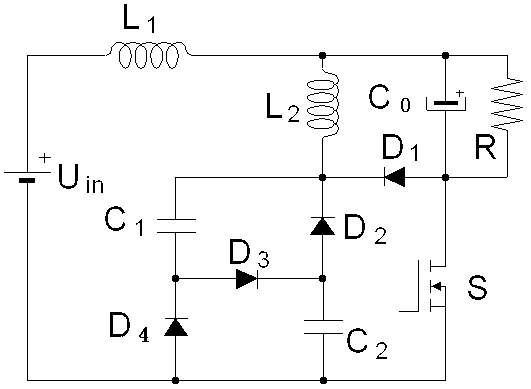
[0024] The present invention provides a voltage-dividing step-down Cuk converter circuit, including a power switch tube S, characterized in that: the control terminal of the power switch tube S is connected to a PWM control signal, and one end of the power switch tube S is used as The negative pole of the output end of the voltage-dividing buck Cuk converter circuit is connected to the negative pole of an output electrolytic capacitor Co and the anode of a diode D1; the cathode of the diode D1 is connected to one end of an inductor L2, one end of a capacitor C1 and A cathode of a diode D2; the positive pole of the output electrolytic capacitor Co is used as the positive pole of the output terminal of the voltage-dividing step-down Cuk converter circuit and is c...


PUM


Abstract

The invention relates to a voltage division step-down Cuk converter circuit which comprises a power switch tube S, a diode D1, a diode D2, a diode D3, a diode D4, a capacitor C1, a capacitor C2, an output electrolytic capacitor Co, an inductor L1 and an inductor L2. The capacitor C1, the capacitor C2, the diode D2, the diode D3 and the diode D4 form a voltage division circuit structure, and a step-down range is widened. The voltage division step-down Cuk converter circuit can realize large step-down change, reasonable PWM (pulse width modulation) duty ratio control and floor control for a switch, and has the advantages of continuous input and output current, low pulse, high circuit conversion efficiency, fine EMI (electro-magnetic interference) effect, convenience in control and the like.

Description

technical field [0001] The invention relates to a step-down Cuk converter circuit, in particular to a voltage-dividing step-down Cuk converter circuit with improved input-output step-down transformation ratio. Background technique [0002] In the fields of LED lighting drive, communication, IPM (Intelligent Power Module) drive, MCU power supply, relay and AC switch power supply, many applications require step-down circuits. Because of its simple structure, low cost, high conversion efficiency and many corresponding commercial control chips, the non-isolated DC-DC converter circuit is widely used in occasions where small and medium power does not require electrical isolation. With the development of technology, these topologies also have limitations in some applications. For example, in applications where the power supply voltage and the voltage required by the electrical equipment have a large step-down ratio, using a traditional non-isolated step-down converter, such as a ...

Claims


Application Information

Patent Timeline
Patent Type & Authority Applications(China)
IPC IPC(8): H02M3/10H02M3/155
Inventor 林维明何宏伟
Owner FUZHOU UNIV
Why Eureka
Try Eureka