
Beam forming method, apparatus and base station equipment

A beamforming method and beamforming technology, applied in space transmit diversity, network planning, electrical components, etc., can solve problems such as directional holes, achieve the effects of improving reliability, ensuring stable communication, and making up for directional holes

Active Publication Date: 2015-07-01
CHINA MOBILE GROUP DESIGN INST
View PDF8 Cites 0 Cited by
  • Summary
  • Abstract
  • Description
  • Claims
  • Application Information

AI Technical Summary

Problems solved by technology

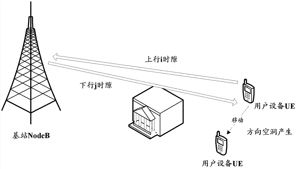
[0015] Embodiments of the present invention provide a beamforming method, device, and base station equipment, which are used to solve the problem of directional holes existing in the existing smart antenna beamforming technology, thereby improving the reliability of beamforming and ensuring stable communication for users

Method used


Image

  • Beam forming method, apparatus and base station equipment
  • Beam forming method, apparatus and base station equipment
  • Beam forming method, apparatus and base station equipment

Examples


Embodiment Construction

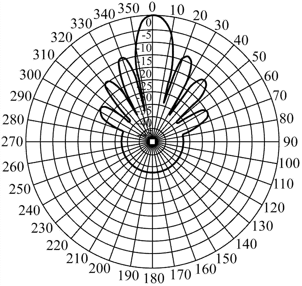
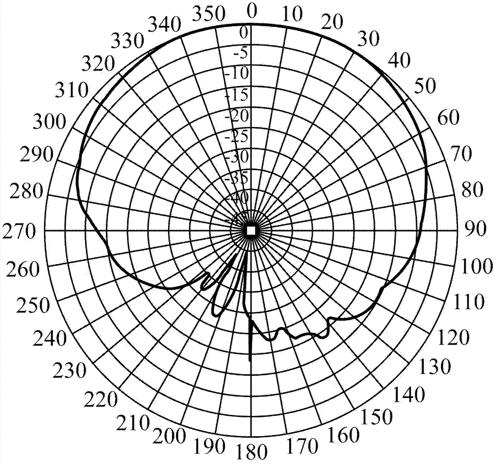
[0036] The embodiment of the present invention aims to provide a robust beamforming method to make up for the directional hole problem existing in the existing smart antenna beamforming technology. The broadcast channel forming vector is introduced into the downlink forming vector, and the broadcast channel forming vector is adopted. The beamforming vector is combined with the main eigendirectional vector of the UE obtained based on uplink channel estimation, so as to suppress cell interference while improving the reliability of beamforming and ensure stable communication for users.

[0037] During the invention process, the inventors found that the existing TDD system includes two kinds of shaped beams: an omnidirectional beam for cell coverage and a shaped beam for UE. Broadcast channels must use omnidirectional beams to cover the entire cell, and traffic channels usually use shaped beams to cover a single UE. Schematic diagram of the beamforming effect of traffic channel be...


PUM


Abstract

The invention discloses a beam forming method, an apparatus and base station equipment, aiming at the problem of a direction cavity in the existing intelligent antenna beam forming technology. The beam forming method comprises the following steps of: acquiring a main characteristic direction vector of user equipment (UE) based on an uplink channel estimation; synthesizing a downlink forming vector by a broadcast channel forming vector and the acquired main characteristic direction vector; and forming the beam loading the downlink data which is transmitted to the UE by the synthesized downlink forming vector. According to the scheme disclosed by the invention, the reliability of the beam forming is enhanced and stable communication of the user is guaranteed.

Description

technical field [0001] The present invention relates to the technical field of wireless communication, in particular to a beam forming method, device and base station equipment. Background technique [0002] Beamforming technology is a linear preprocessing technology based on small-pitch antenna arrays. It can adjust the excitation of each antenna element in the antenna array according to the user's channel characteristics, so that the shape of the antenna beam pattern becomes a specified beam shape, thereby To achieve the purpose of expanding coverage, improving system capacity, and reducing interference. [0003] TDD (Time Division Duplex, Time Division Duplex) mobile communication system is TDD system, such as TD-SCDMA (Time Division Synchronous CDMA, Time Division Synchronous CDMA; CDMA: Code Division Multiple Access, Code Division Multiple Access) system, TD-LTE (TD-SCDMA Long Term Evolution, long-term evolution of TD-SCDMA) system, LTE-A (LTE-Advanced) system, etc., u...

Claims


Application Information

Patent Timeline
Patent Type & Authority Patents(China)
IPC IPC(8): H04B7/04H04W16/28H04W88/08
Inventor 张华张新程贾东燕汤利民赵旭凇白承灏郭晓鹏徐德平胡恒杰赵海宁李源
Owner CHINA MOBILE GROUP DESIGN INST
Learn More