Supercharge Your Innovation With Domain-Expert AI Agents!

Optical fiber autocoupling pairing system for optical module test

An optical module testing and automatic coupling technology, applied in the field of optical fiber communication, can solve the problems of error-prone, time-wasting, manpower, low efficiency, etc., and achieve the effect of saving manpower and station time, and improving test efficiency

Active Publication Date: 2013-04-03
SOURCE PHOTONICS CHENGDU
View PDF3 Cites 16 Cited by
  • Summary
  • Abstract
  • Description
  • Claims
  • Application Information

AI Technical Summary

Problems solved by technology

However, manually connecting and matching the optical module to be tested with the corresponding optical channel of the multi-channel optical switch is inefficient, error-prone, and wastes time and manpower.

Method used


Image

  • Optical fiber autocoupling pairing system for optical module test
  • Optical fiber autocoupling pairing system for optical module test

Examples


Embodiment Construction

[0014] The present invention will be further described in detail below in conjunction with test examples and specific embodiments. However, it should not be understood that the scope of the above subject matter of the present invention is limited to the following embodiments, and all technologies realized based on the content of the present invention belong to the scope of the present invention.

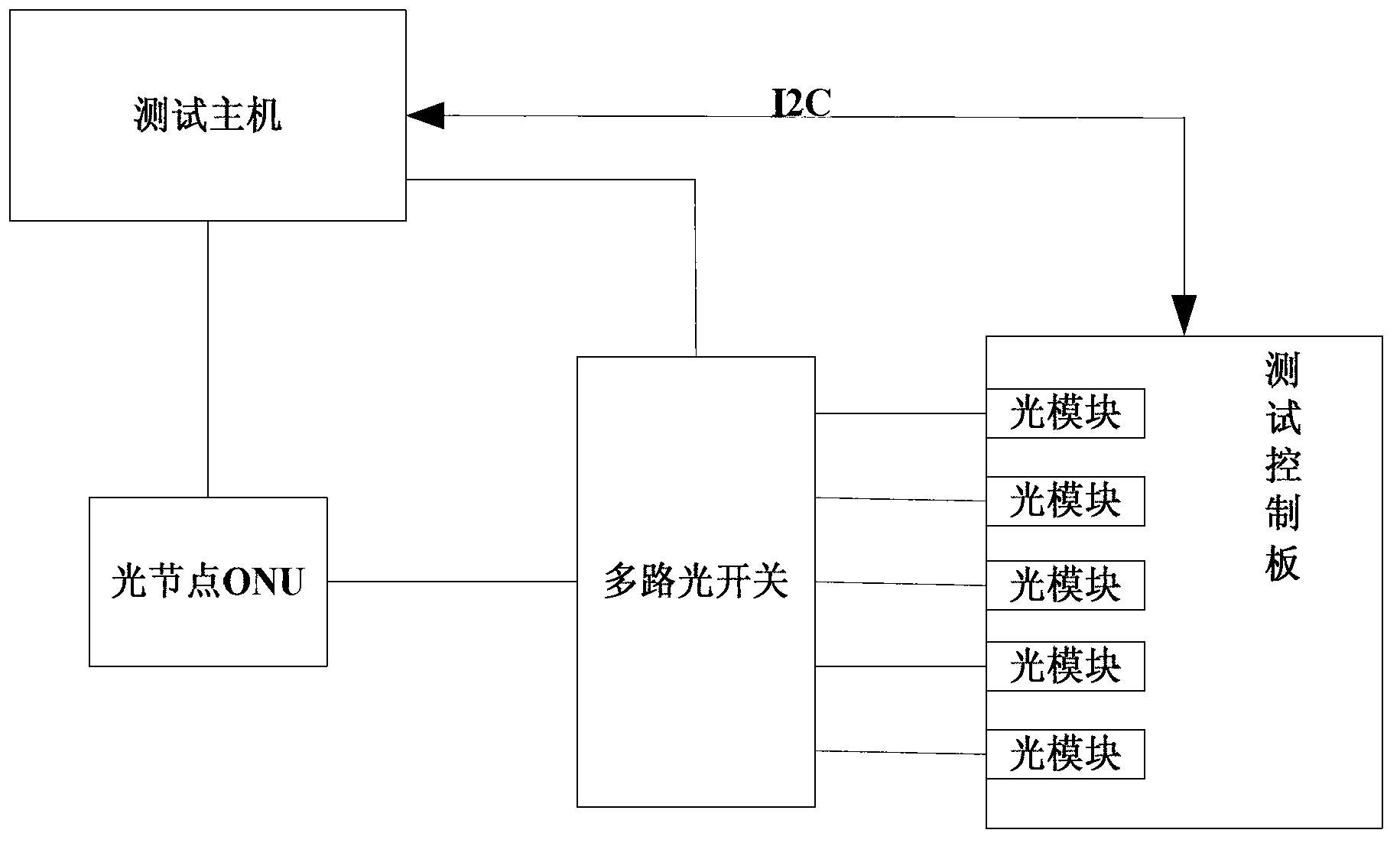
[0015] like figure 1 As shown, the optical fiber automatic coupling and pairing system in the optical module test of the present invention includes a test host, an optical node ONU, a multi-channel optical switch, a test control board and a plurality of optical modules installed on the test control board; The optical switch is connected to a plurality of optical modules through optical fibers, each optical channel of the multi-channel optical switch corresponds to an optical module, the test control board is connected to a test host, and the test host is connected to the multi-chann...


PUM


Abstract

The invention discloses an optical fiber autocoupling pairing system for an optical module test. The optical fiber autocoupling pairing system comprises a test mainframe, an ONU (optical network unit), a multiway optical switch, a test control panel and a plurality of optical modules mounted on the test control panel. The multiway optical switch is connected with the optical modules through optical fibers, each optical channel of the multiway optical switch corresponds to one optical module, the test control panel is connected with the test mainframe which is connected with the multiway optical switch, and the test mainframe is further connected with the multiway optical switch through the ONU. By means of the optical fiber autocoupling pairing system for the optical module test, a great deal of manpower and station time is saved, and optical module test efficiency is improved greatly.

Description

technical field [0001] The invention relates to the field of optical fiber communication, in particular to an optical fiber automatic coupling and pairing system in optical module testing. Background technique [0002] When testing optical modules in the prior art, in order to improve the test efficiency, multiple optical modules to be tested are installed on the test board. The test board is connected to control the test board to test multiple optical modules. Before the test, the operator needs to accurately find out which optical module corresponds to the corresponding optical channel of the multi-channel optical switch when connecting the multi-channel optical switch and multiple optical modules through optical fibers, which is convenient for accurate recording and storage of test data. However, manually connecting and matching the optical module to be tested with the corresponding optical channel of the multi-channel optical switch is inefficient, error-prone, and wast...

Claims


Application Information

Patent Timeline
IPC IPC(8): H04B10/07
Inventor 古颖泉陈晓鹏胡云克瑞斯·劳鲍特
Owner SOURCE PHOTONICS CHENGDU
Features
  • R&D
  • Intellectual Property
  • Life Sciences
  • Materials
  • Tech Scout
  • Unparalleled Data Quality
  • Higher Quality Content
  • 60% Fewer Hallucinations
Learn More