

Construction for mounting ultrasonic transducer and ultrasonic flow meter using same
An installation structure, ultrasonic technology, applied in the direction of measuring flow/mass flow, liquid/fluid solid measurement, instruments, etc., can solve the problem of high cost
- Summary
- Abstract
- Description
- Claims
- Application Information
AI Technical Summary
Problems solved by technology
Method used
Image

Examples
Embodiment approach 1
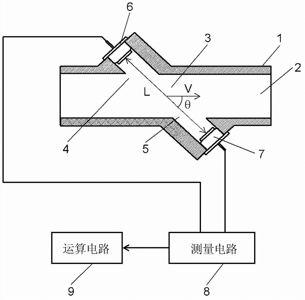
[0027] figure 1 It is a figure which shows the structure of the ultrasonic flowmeter which used the mounting structure of the ultrasonic transceiver which concerns on 1st Embodiment of this invention.
[0028] exist figure 1 In the flow path 2 formed on the casing 1, fluids such as LP gas and natural gas flow. The flow measurement part 3 is an area for measuring the flow rate of the fluid flowing in the flow path 2. At the flow measurement part 3, an ultrasonic transceiver 6 is arranged on the upstream side 4 of the flow path 2, and an ultrasonic transceiver 6 is arranged on the downstream side 5 of the flow path 2. An ultrasonic transceiver 7 is provided.
[0029] Ultrasonic transceiver 6 and ultrasonic transceiver 7 are connected with measuring circuit 8, and this measuring circuit 8 is used for measuring the ultrasonic propagation time between ultrasonic transceiver 6 and ultrasonic transceiver 7, and is provided with computing circuit 9, and this computing circuit 9 T...
Embodiment approach 2
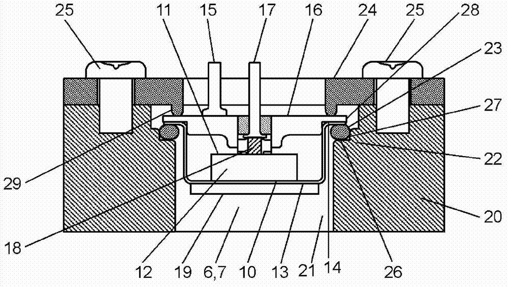
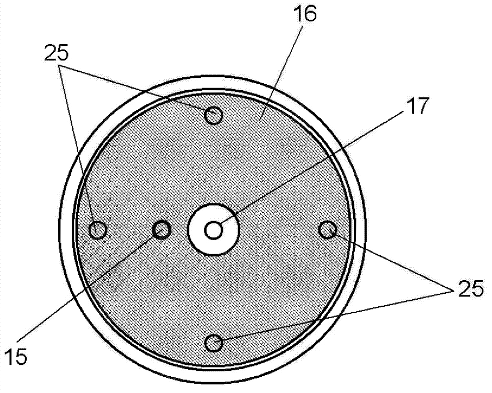
[0051] Figure 4 , Figure 5 It is a figure which shows the 2nd Embodiment of this invention, Figure 4 is a diagram showing a mounting sectional view of an ultrasonic transceiver, Figure 5 It is the top view of the installation of the ultrasonic transceiver.
[0052] exist Figure 4 Among them, on the top of the stepped portion 31 of the casing 30, there are four protrusions 32 as abutment limiting parts. When the ultrasonic transceivers 6, 7 are inserted into the O-ring 34 of the mounting hole 33, This protrusion 32 prevents the outer peripheral portion 36 of the terminal plate 35 from coming into contact with the side wall portion 30 a of the housing 30 . In addition, the protrusion 32 is shaped to be in contact with the outer peripheral portion 36 of the terminal plate 35 in a longitudinal linear shape. Other structures and assembly methods with figure 2 Same, description omitted.
[0053] In the present embodiment, when the ultrasonic transducers 6 and 7 are urge...
Embodiment approach 3
[0057] Figure 6 It is a figure which shows the 3rd embodiment of this invention, Figure 6 is the installation cutaway view of the ultrasonic transceiver. exist Figure 6 Among them, the urging member 37 has a protruding portion 39 and a supporting portion 41, and the protruding portion 39 is in contact with at least three positions of the terminal board 38 of the ultrasonic transceiver 6, 7, and exerts force on the terminal board 38. The portion 41 is in contact with the outer peripheral portion 38 a of the terminal plate 38 at at least three positions, and supports the ultrasonic transducers 6 , 7 toward the center of the mounting hole 40 . The structure and assembly method of the O-ring 42 as other components, the housing 43, the screws 44 as the locking components, etc. figure 2 Same, description omitted.
[0058] In the present embodiment, when the ultrasonic transceivers 6 and 7 are urged by the protrusions 39 of the biasing member 37, the outer peripheral portion ...
PUM
 Abstract
Description
Claims
Application Information