Method and frames for taking out broken rolls of upper working roll

A technology for work rolls and roll breakage, applied in manufacturing tools, metal rolling stands, metal processing equipment, etc., can solve the problems of difficult removal of upper work rolls and backup rolls, lack of falling fulcrums, and increased risk of roll breakage, etc. Achieve the effect of low production cost, reduce the risk of secondary accidents, and reduce the loss of production stoppage

Active Publication Date: 2014-12-03
ANGANG STEEL CO LTD
View PDF6 Cites 0 Cited by
  • Summary
  • Abstract
  • Description
  • Claims
  • Application Information

AI Technical Summary

Problems solved by technology

[0002] With the continuous upgrading of the product structure of the hot rolling line, the load of finishing rolling is increasing, and the risk of roll breakage is increasing. Due to the lack of special tools for taking out broken rolls, the method of pulling and pulling can only be used. The processing time for each accident is between 8 to 12 hours, causing huge economic losses
[0003] Among various broken roll accidents, the breakage of the upper work roll and backup roll is the most difficult to take out, because the lack of falling fulcrum makes it prone to tipping and slipping accidents during the pulling out process
At present, tools and technologies for quickly removing the upper support roll are available, but there is still a lack of a tool for safely and quickly removing the broken upper work roll, which can remove two to three broken rolls at one time, and effectively prevent instability and slipping during the process

Method used


Image

  • Method and frames for taking out broken rolls of upper working roll
  • Method and frames for taking out broken rolls of upper working roll
  • Method and frames for taking out broken rolls of upper working roll

Examples


Embodiment Construction

[0021] The specific embodiment of the present invention will be further described below in conjunction with accompanying drawing:

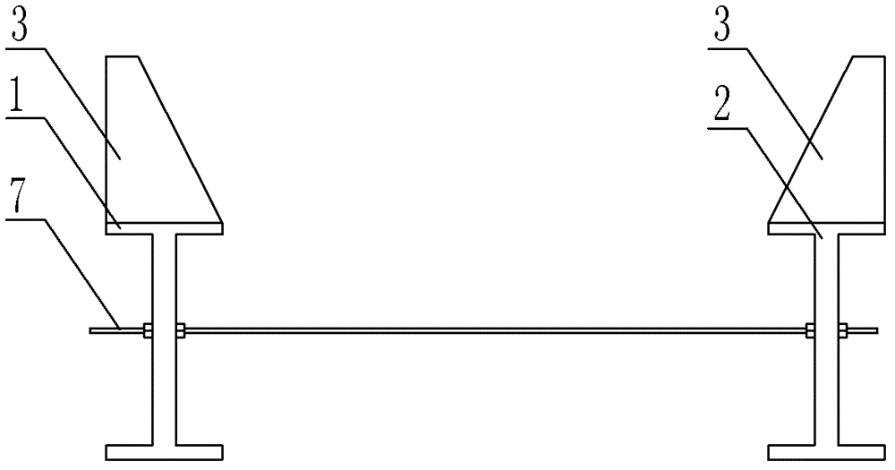
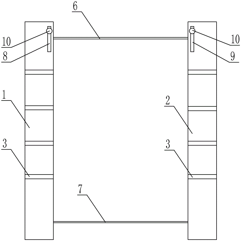
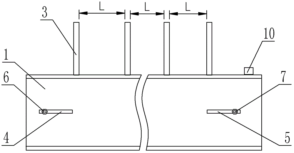
[0022] See figure 1 , is a structural schematic diagram of an embodiment of a broken roll take-out frame of the present invention, including a longitudinal beam 1, a longitudinal beam 2 and a trapezoidal supporting plate 3, and the relative positions of the longitudinal beam 1 and the longitudinal beam 2 are respectively provided with a long hole 4 With elongated hole two 5, be provided with bolt one 6 in elongated hole one 4, be provided with bolt two 7 in elongated hole two 5, bolt one 6 and bolt two 7 can adjust position along elongated hole one 4 and elongated hole two 5, with Adapt to different work roll structures on the seven racks, and apply anti-rust oil to the bolt position when not in use to prevent function failure. The first longitudinal beam 1 and the second longitudinal beam 2 are symmetrically provided with trapezoidal supporting ...


PUM


Abstract

The invention relates to the field of finishing mill group, in particular to a method and frames for taking out broken rolls of an upper working roll. The method and the frames for taking out the broken rolls of the upper working roll are characterized in that the upper working roll broken into two to three segments is taken out for once through automatic drawing-out functions of a lower working roller and the operation steps are as follows: (1) fitting an upper working roll balance cylinder to lift up the upper working roll; (2) drawing out the lower working roll, and lifting and carrying the frames for taking out the broken rolls to positions between clamp grooves of the lower working roller; (3) adjusting positions of bolts on the frames for taking out the broken rolls to respectively clamp the contact clamp grooves; (4) operating the lower working roller on a rolling mill and ensuring that the upper working roller slowly falls onto the frames for taking out the broken rolls according to procedures of changing rollers; (5) drawing out the upper working roller and the lower working roller at the same time and replacing a new upper working roller. Compared with the prior art, the method and the frames for taking out the broken rolls of the upper working roll have the advantages that the several frames with different structures are universally applied in the structure of the finishing mill group and shorten accident handling time to one-two hours by utilizing the automatic drawing-out functions of the lower working roller, and therefore maintenance efficiency is greatly improved.

Description

technical field [0001] The invention relates to the field of maintenance of finishing rolling mills, in particular to a method for taking out broken upper work rolls and a stand for taking out broken rolls. Background technique [0002] With the continuous upgrading of the product structure of the hot rolling line, the load of finishing rolling is increasing, and the risk of roll breakage is increasing. Due to the lack of special tools for taking out broken rolls, the method of pulling and pulling can only be used. The processing time for each accident is between 8 to Between 12 hours, huge economic losses were caused. [0003] Among various broken roll accidents, the breakage of the upper work roll and backup roll is the most difficult to take out. The reason is that there is a lack of falling fulcrum, and accidents of tipping and slipping are prone to occur during the pulling out process. At present, tools and technologies for quick removal of the upper support roll are a...

Claims


Application Information

Patent Timeline
Patent Type & Authority Patents(China)
IPC IPC(8): B21B31/08
Inventor 文新理张福多韩庆李庆贤周新亮王健
Owner ANGANG STEEL CO LTD
Why Eureka
Try Eureka