Rocker shaft bore-deburring machine

A rocker shaft and deburring machine technology, which is applied to reaming devices, reaming devices, metal processing machinery parts, etc., can solve the problems of increased cost and low deburring efficiency, and achieve low labor intensity, simple operation and high efficiency Effect

Active Publication Date: 2013-04-10
ZHEJIANG QIANGNENG MOTIVITY
View PDF11 Cites 9 Cited by
  • Summary
  • Abstract
  • Description
  • Claims
  • Application Information

AI Technical Summary

Problems solved by technology

Using the above-mentioned deburring method, the efficiency of deburring is low, which will undoubtedly increase the cost

Method used


Image

  • Rocker shaft bore-deburring machine
  • Rocker shaft bore-deburring machine
  • Rocker shaft bore-deburring machine

Examples


Embodiment Construction

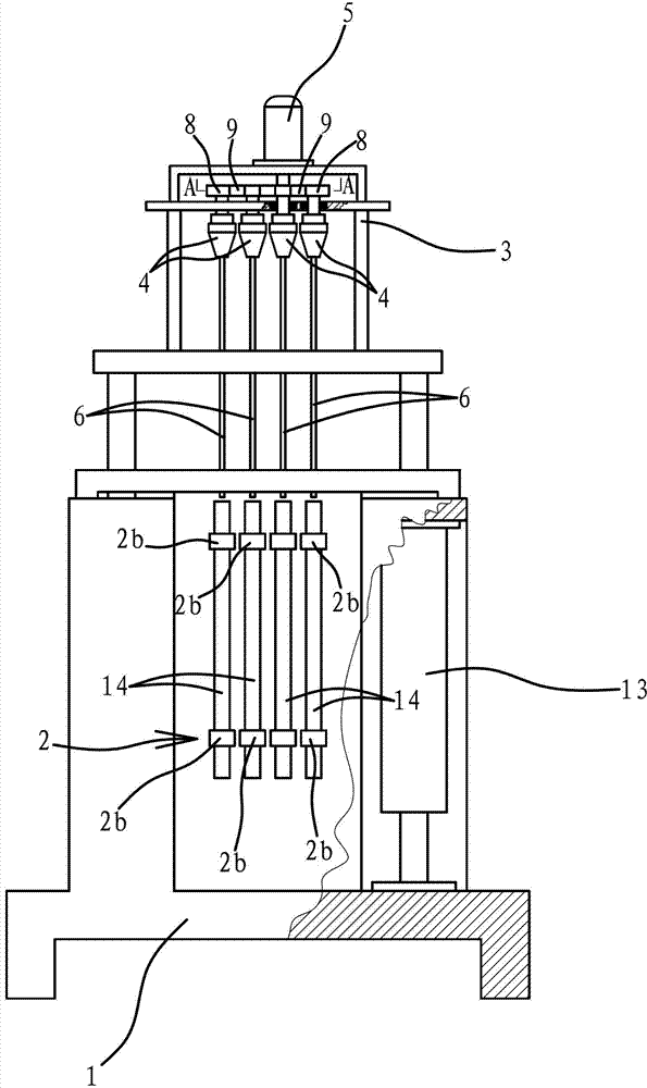
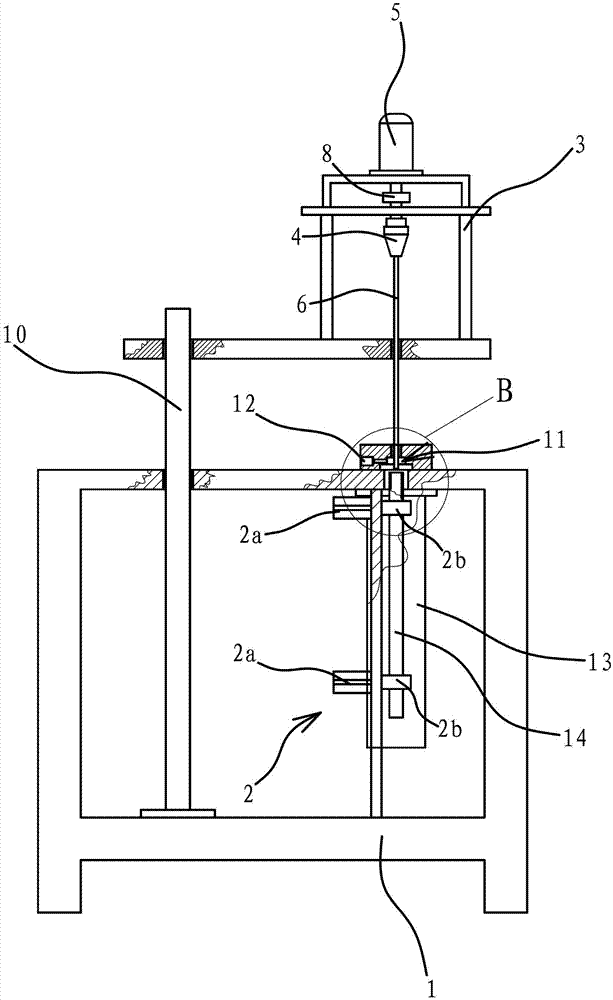
[0032]The following are specific embodiments of the present invention and in conjunction with the accompanying drawings, the technical solutions of the present invention are further described, but the present invention is not limited to these embodiments.

[0033] like Figures 1 to 5 As shown, a rocker shaft inner hole deburring machine includes a base 1, and four clamping mechanisms 2 are arranged on the base 1. The clamping mechanism 2 includes two V-shaped chucks 2b and can drive the corresponding V-shaped chucks 2b Two air cylinders 2a for opening and closing, the cylinder body of the air cylinder 2a are all connected on the base 1 . The rocker shaft 14 is clamped by the two V-shaped chucks 2b, so that when the rocker shaft 14 is fixed on the V-shaped chuck 2b, it can be kept facing the tool 6, which has a better positioning effect. As another solution, the clamping mechanism 2 is a clamping cylinder 2 a fixedly connected to the base 1 , and the jaws of the clamping cyli...


PUM


Abstract

The invention provides a rocker shaft bore-deburring machine, which belongs to the technical field of mechanical equipment. The invention solves the problems of the conventional deburring method, i.e. low deburring efficiency and high cost. The rocker shaft bore-deburring machine comprises a base, clamping mechanisms which can clamp rocker shafts are arranged on the base, a tool holder is also arranged on the base, tool chucks and a motor capable of driving the tool chucks to rotate are axially and fixedly connected with the tool holder, one end of each tool chuck is fixedly connected with a tool, the tools are aligned with the bores of the rocker shafts when the rocker shafts are clamped by the clamping mechanism, the motor is connected with the other ends of the tool chucks in a transmission way, and a driving mechanism which can drive the tool holder to move to cause the tools to reciprocate in a manner relative to the rocker shafts is also arranged on the base. The rocker shaft bore-deburring machine has the advantages of high machining efficiency, high stability and the like.

Description

technical field [0001] The invention belongs to the technical field of mechanical equipment, and relates to a deburring machine, in particular to a rocker shaft inner hole deburring machine. Background technique [0002] The rocker arm of the engine is fixed on the rocker arm bracket through the rocker arm shaft, and the rocker arm bracket is fixed on the cylinder of the engine. The existing rocker shaft is a straight rod, the middle part of the straight rod has a through hole along its axial direction, and the side of the straight rod is provided with several oil holes, so that the lubricating oil can enter the gap between the rocker shaft and the rocker arm and lubricate the contact surfaces of the two. [0003] For example, a new type of valve rocker shaft [Application No.: 201020140915.X; authorized announcement number: CN 201661325U] proposed in Chinese patent documents, the rocker shaft includes a shaft body, and a through hole is provided at the central axis of the s...

Claims


Application Information

Patent Timeline
Patent Type & Authority Applications(China)
IPC IPC(8): B23D75/00B23D79/00B23Q5/26B23Q11/00B23Q11/10
Inventor 方福忠
Owner ZHEJIANG QIANGNENG MOTIVITY
Why Eureka
Try Eureka