Movable in-row template

A template and limiting plate technology, which is applied in molds, ceramic molding machines, manufacturing tools, etc., can solve the problems of high production cost, complex system structure, and high requirements for site conditions, and meet the requirements of low production cost, small size, and production site conditions low effect

Active Publication Date: 2015-04-22
蒋卓
View PDF5 Cites 0 Cited by
  • Summary
  • Abstract
  • Description
  • Claims
  • Application Information

AI Technical Summary

Problems solved by technology

[0003] The purpose of the present invention is to solve the problems of complex system structure, high production cost and high requirements on site conditions existing in the prior art, and proposes a movable formwork

Method used


Image

  • Movable in-row template
  • Movable in-row template
  • Movable in-row template

Examples


Embodiment Construction

[0014] The present invention will be further described below in conjunction with the accompanying drawings.

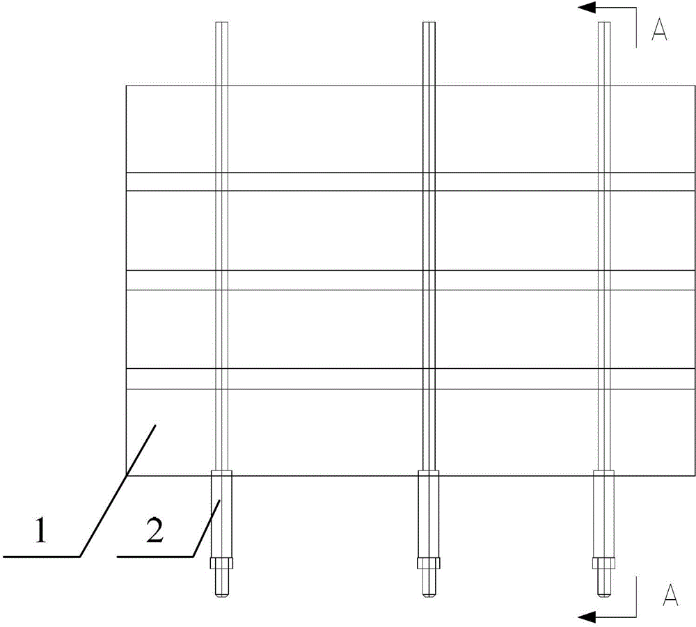
[0015] See attached figure 1 , attached figure 2 , attached image 3 , attached Figure 4 and Figure 5 , the movable formwork of the present invention includes U-shaped steel molds 1 and fasteners 2, and a plurality of U-shaped steel molds 1 are welded end to end to form a unit mold, and four groups of said unit molds are connected by three said fastening elements. Pieces 2 are connected side by side. The fasteners 2 adjust the fastening amount by tightening the nuts 204 when the template is fastened, and the three fasteners 2 are arranged in parallel; the fasteners 2 include a lead screw 202, a limit plate 201 , a movable limiting plate 203 and a nut 204, the limiting plate 201 is fixedly connected with one end of the lead screw 202, the movable limiting plate 203 is connected with the other end of the leading screw 202 with clearance fit, the A screw pair is ...


PUM


Abstract

The invention discloses a movable in-row template, belonging to the technical field of building engineering and aiming at solving the problems of complex system structure, high manufacturing cost and high requirement for site condition in the prior art. The movable in-row template comprises U-shaped steel dies and fasteners, wherein a plurality of the U-shaped steel dies are welded into a whole body in an end-to-end manner to form a unit die; n unit dies are connected in a side-by-side manner by the fasteners; each fastener comprises a lead screw, a limiting plate, a movable limiting plate and a nut; each limiting plate is fixedly connected with one end of the related lead screw; each movable limiting plate is in clearance fit with the other end of the related lead screw; a spiral pair is formed between each nut and the related lead screw; and the position of each nut is adjusted to realize adjustment of the distance between each limiting plate and the related movable limiting plate. The movable in-row template disclosed by the invention has the advantages that the mechanical connection among all the unit dies is realized by the fasteners, the system mechanism is simple, the manufacturing cost is low, the requirement for the condition of multiple production places, the installation is flexible, and the production mode for instantaneous use after unloading can be realized.

Description

technical field [0001] The invention belongs to the technical field of construction engineering, and in particular relates to a movable row formwork. Background technique [0002] At present, most of the formwork materials used in the production of reinforced concrete prefabricated components are bamboo formwork and wood formwork, and each formwork is supported by one component. The Chinese patent with the application number CN200910067305.3 discloses a technical solution named "Prefabricated square pile conjoined steel mold automatic demoulding system", which consists of multiple parallel single U-shaped steel molds. The head and tail of the single U-shaped steel mold are connected as a whole through steel plates to form a unit combined steel mold, which is driven and squeezed together by a hydraulic drive system to form a whole. This kind of integrated steel mold is driven by hydraulic pressure to make the unit combined steel mold into one, which leads to the problems of ...

Claims


Application Information

Patent Timeline
Patent Type & Authority Patents(China)
IPC IPC(8): B28B7/22B28B7/24
Inventor 高广财
Owner 蒋卓
Why Eureka
Try Eureka