An electronically controlled shift controller for a loader gearbox

A technology of loader and gearbox, applied in transmission control, mechanical equipment, components with teeth, etc., can solve the problems of controller burning, complicated shifting mechanism, and high labor intensity of drivers.

Active Publication Date: 2016-05-25
龙工(上海)机械制造有限公司
View PDF5 Cites 0 Cited by
  • Summary
  • Abstract
  • Description
  • Claims
  • Application Information

AI Technical Summary

Problems solved by technology

The domestically newly developed multi-gear gearboxes with four advances and three retreats and four advances and four retreats have many gears. If the mechanical-hydraulic control method is adopted, not only the shifting mechanism is too complicated, but also the operating force is large, causing the driver to work hard. High strength, low operating efficiency, and it is difficult to realize functions such as neutral start protection, neutral lock, reverse alarm and power cutoff
[0003] At present, the controller used by the domestically-made electronically controlled shift loader has defects in circuit protection. Because there are many electrical appliances in the whole machine, the instantaneous voltage can sometimes reach a very high peak value, causing the controller to burn out. The protection against electromagnetic interference is defective, resulting in faults such as sometimes lack of gears and disordered gears, and these controllers are generally heavy and clumsy in appearance

Method used


Image

  • An electronically controlled shift controller for a loader gearbox
  • An electronically controlled shift controller for a loader gearbox
  • An electronically controlled shift controller for a loader gearbox

Examples


Embodiment Construction

[0091] In order to make the present invention more comprehensible, preferred embodiments are described in detail below with accompanying drawings.

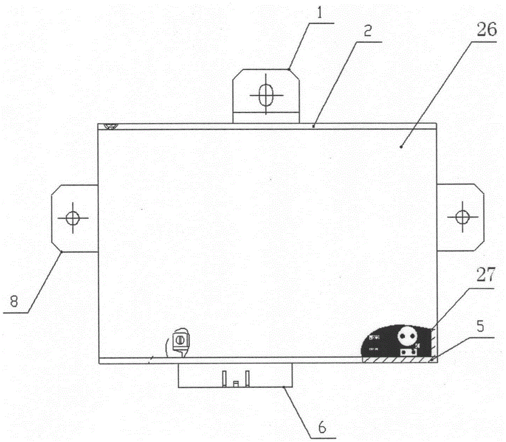
[0092] Such as figure 1 As shown, the present invention provides an electronically controlled shift controller for a loader gearbox, which includes a housing 26, a circuit unit 27 is arranged in the housing 26, and a mounting plate 1 and a mounting plate 8 are arranged on the housing 26. The casing 26 has a rear cover 2 and a front cover 5 . Wherein the mounting plate 1 and the mounting plate 8 are fixed by triangle irons, and the whole is simple and elegant. The back cover 2, the front cover 5 and the housing 26 are waterproofed, and the plug-in itself has excellent waterproof performance and is easy to insert and remove.

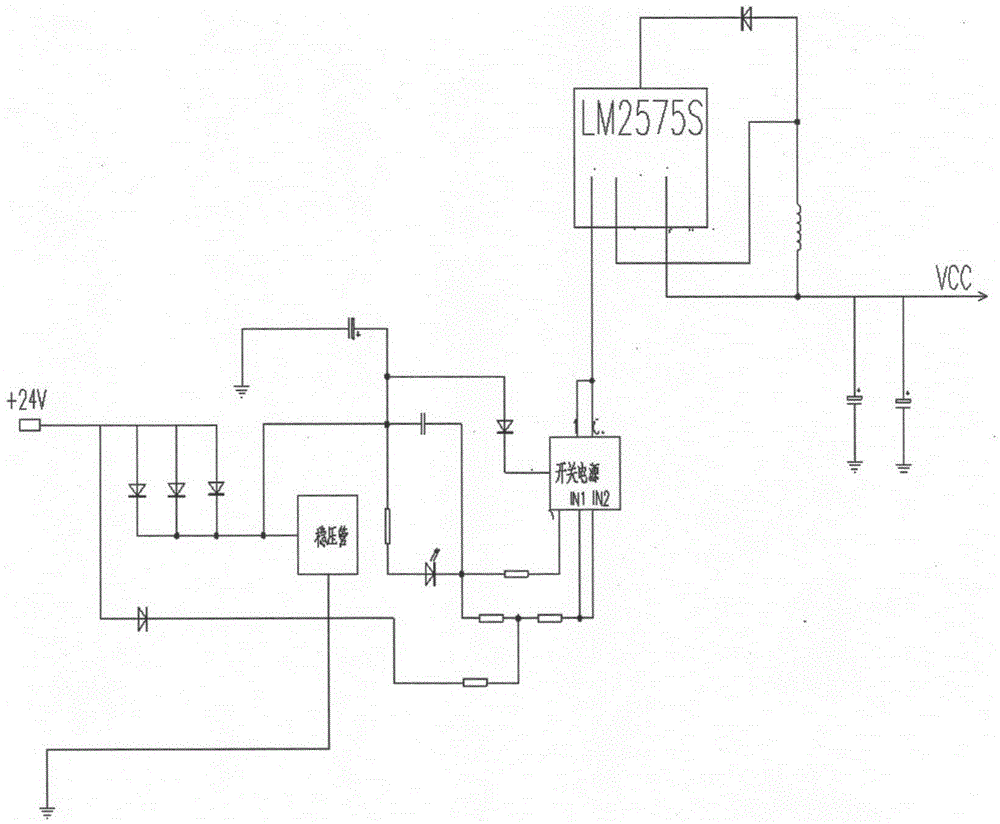
[0093] The circuit unit 27 includes a logic control module and a power supply module that provides a DC voltage VCC for the logic control module, wherein:

[0094] Such as figure 2As shown, the power modu...


PUM


Abstract

The invention relates to an electric control gear-shifting controller of a transmission gearbox of a loader. The electric control gear-shifting controller comprises a shell, wherein a circuit unit is arranged in the shell, and a mounting plate is arranged on the shell. The electric control gear-shifting controller is characterized in that the circuit unit comprises a logic control module and a power supply module for providing a direct-current voltage for the logic control module, wherein the logic control module is achieved by a logic circuit and is provided with 8 input ends, each input end corresponds to the output end of a gear-shifting handle, and the logic control module controls a corresponding electromagnetic valve in electric control speed-changing operating valves to enter an on state according to the output of the gear-shifting handle so as to enable corresponding gears of a clutch to combine to realize gear-shifting. The electric control gear-shifting controller of the transmission gearbox of the loader, disclosed by the invention, has the advantages of effectively protecting a complete electric appliance and avoiding electromagnetic interference.

Description

technical field [0001] The invention relates to an electronically controlled shift controller for a loader gearbox. Background technique [0002] Most domestic wheel loaders use gear-type power shift transmissions, which are basically equipped with two-into-one-reverse or three-into-three-reverse power-shift transmissions. This kind of transmission generally uses a mechanical-hydraulic system with a flexible shaft or a space hinge mechanism. way to control. The domestically newly developed multi-gear transmission with four advances and three retreats and four advances and four retreats has many gears. If the mechanical-hydraulic control method is adopted, not only the shifting mechanism is too complicated, but also the operating force is large, causing the driver to work hard. The strength is high, the operation efficiency is low, and it is difficult to realize functions such as neutral gear start protection, neutral gear lock, reverse alarm and power cut-off. [0003] At ...

Claims


Application Information

Patent Timeline
Patent Type & Authority Patents(China)
IPC IPC(8): F16H59/02F16H61/18F16H61/28
Inventor 詹永红梅宇清刘霞王孙濂陈超
Owner 龙工(上海)机械制造有限公司
Why Eureka
Try Eureka