Eureka AIR delivers breakthrough ideas for toughest innovation challenges, trusted by R&D personnel around the world.

Vehicle speed real-time detection method with field programmable gate array (FPGA)

A real-time detection and vehicle speed detection technology, which is applied in the field of signal processing and can solve the problems of difficult to ensure consistent gaps, unstable signal amplitude, and unclean vehicle speed signals.

Inactive Publication Date: 2014-12-10
CHINA NORTH VEHICLE RES INST
View PDF5 Cites 0 Cited by
  • Summary
  • Abstract
  • Description
  • Claims
  • Application Information

AI Technical Summary

Problems solved by technology

Therefore, in order to obtain a stable speed signal, it is necessary to limit and amplify the output signal of the magnetoelectric sensor; because the installation gap of the magnetoelectric speed sensor has a great influence on the amplitude of the output signal, and in actual engineering installation, the gap It is difficult to ensure consistency, therefore, the amplitude of the signal is very unstable
Due to the above reasons, the amplified and shaped signal of the output signal of the magnetoelectric sensor often contains noise and contains transient pulse glitches.
For military vehicles, such as tank vehicles, because many electrical systems work at the same time, the power supply voltage is very unstable, which will cause the vehicle speed signal to be very "clean", which brings difficulties to the real-time detection of the test
[0004] For the Hall-type speed sensor, its anti-interference ability is poor, and the output pulse has too much interference. It is difficult to solve the anti-interference problem with the traditional counting method and periodic measurement method, so it is rarely used in vehicle speed detection.

Method used


Image

  • Vehicle speed real-time detection method with field programmable gate array (FPGA)
  • Vehicle speed real-time detection method with field programmable gate array (FPGA)

Examples


Embodiment

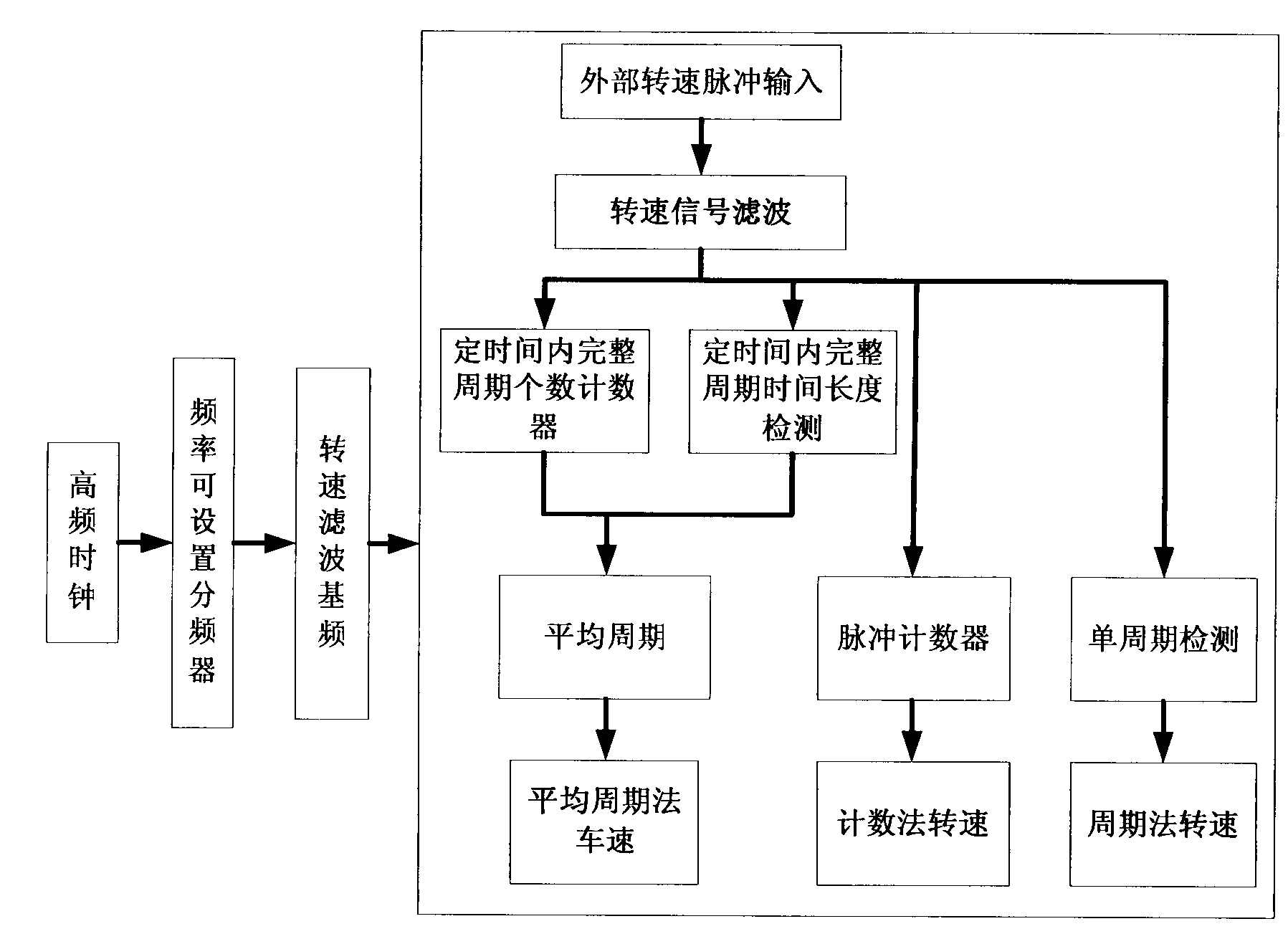
[0045] In this embodiment, the FPGA is programmed, and then the programming result is downloaded to the FPGA, so that the FPGA can detect the rotational speed signal in the form of chip hardware. Such as figure 1 As shown, the detection of the speed by the FPGA chip is divided into two stages. The first stage is the generation of the detection clock. According to the frequency range of the on-site speed pulse, the benchmark for speed pulse detection is also different. This frequency is the same as the gear that generates the speed pulse. The number of teeth is related to the speed range. For example, when the number of gears is large, the natural speed frequency is high. The corresponding high base frequency can be set within 1KHz ~ 20KHz. On the contrary, the high base frequency can be set In the range of 10Hz to 200Hz; the second stage is based on the clock of the first stage. First, the external speed pulse is filtered, and then the processed pulse is detected synchronously...


PUM


Abstract

The invention relates to a vehicle speed real-time detection method with field programmable gate array (FPGA) and belongs to the technical field of signal processing. In order to resolve problems existing in the prior art, the vehicle speed real-time detection method with FPGA is utilized, through predetermining fundamental frequency, eliminating noise interference, and combining detection schemes, the vehicle speed real-time detection is effectively achieved, especially when field interference is very serious and requirements of precision and reliability of real-time detection are demanding, such as a real-time magnetoelectric vehicle speed signal detection and a magnetoelectric tachometric pulse signal detection. A signal real-time cycle detection method is applied in the vehicle control technology, so that a vehicle speed is detected effectively, and not only is the requirement of being real-time is satisfied, but also the requirement of stability is satisfied. The vehicle speed real-time detection method with FPGA is particularly suitable for detecting a military vehicle speed signal. When the vehicle speed real-time detection method with FPGA is used, work efficiency and work precision of a magnetoelectric tachometric transducer and a Hoare tachometric transducer are improved significantly.

Description

technical field [0001] The invention belongs to the technical field of signal processing, and in particular relates to a method for real-time detection of vehicle speed by using FPGA. Background technique [0002] At present, there are two main types of detection methods for vehicle speed detection: one is to use the pulse counting method to calculate the vehicle speed by detecting the number of pulses that can be obtained within a certain period of time. The advantage of this method is that the detection of anti-interference ability is relatively Strong, a small number of pulse errors will not cause the detection result to fail. The disadvantage is that the detection result is the average result of a period of time, so the real-time performance is relatively poor; another method is to detect the period of the instantaneous pulse to obtain the vehicle speed. The advantage is that the real-time performance is good, but if there is a wrong pulse, it will lead to wrong detectio...

Claims


Application Information

Patent Timeline
Patent Type & Authority Patents(China)
IPC IPC(8): G01P3/42
Inventor 凌云钱锐李春艳王鑫磊王珊胡建军李杰陈旺李耀伟李晴张领辉苏瑾刘春生
Owner CHINA NORTH VEHICLE RES INST
Why Eureka
Eureka Blog
Learn More