
Tester wiring concentration conversion device for vehicle

The technology of a conversion device and a tester, which is applied to the casing of the measuring device and other directions, can solve the problems of waste of manpower and material resources, long waiting time, and many times of climbing, and achieve the effect of convenient use and simple structure.

Inactive Publication Date: 2013-04-10
STATE GRID JIANGSU ELECTRIC POWER CO ELECTRIC POWER RES INST +3
View PDF5 Cites 12 Cited by
  • Summary
  • Abstract
  • Description
  • Claims
  • Application Information

AI Technical Summary

Problems solved by technology

[0002] At present, conventional high-voltage test power comprehensive test vehicles are generally equipped with transformer DC resistance tester, transformer ratio tester, and transformer on-load tap-changer tester. These three instruments have four sets of test lines Aa, Bb, and Cc respectively. , Oo, the conventional method in the past was to connect the four sets of wires of the instruments to the tested product from the four instruments respectively. The three instruments have different lines and different connection methods. The electric power converted in this way There are many wiring on the car, wiring once for a single test item, many times of climbing, high probability of potential safety hazards, many types of test lines, and long time spent on rewinding and unwinding. The long waiting time at the test site prolongs the power outage time of the substation, resulting in a waste of manpower and material resources

Method used


Image

  • Tester wiring concentration conversion device for vehicle
  • Tester wiring concentration conversion device for vehicle
  • Tester wiring concentration conversion device for vehicle

Examples


Embodiment Construction

[0015] The present invention will be described in detail below in conjunction with the drawings, and the following embodiments can enable those skilled in the art to better understand the present invention, but do not limit the present invention in any form.

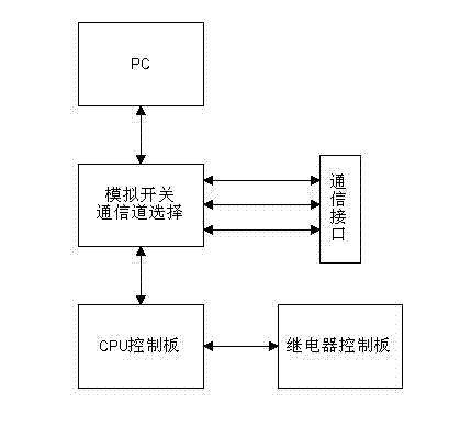
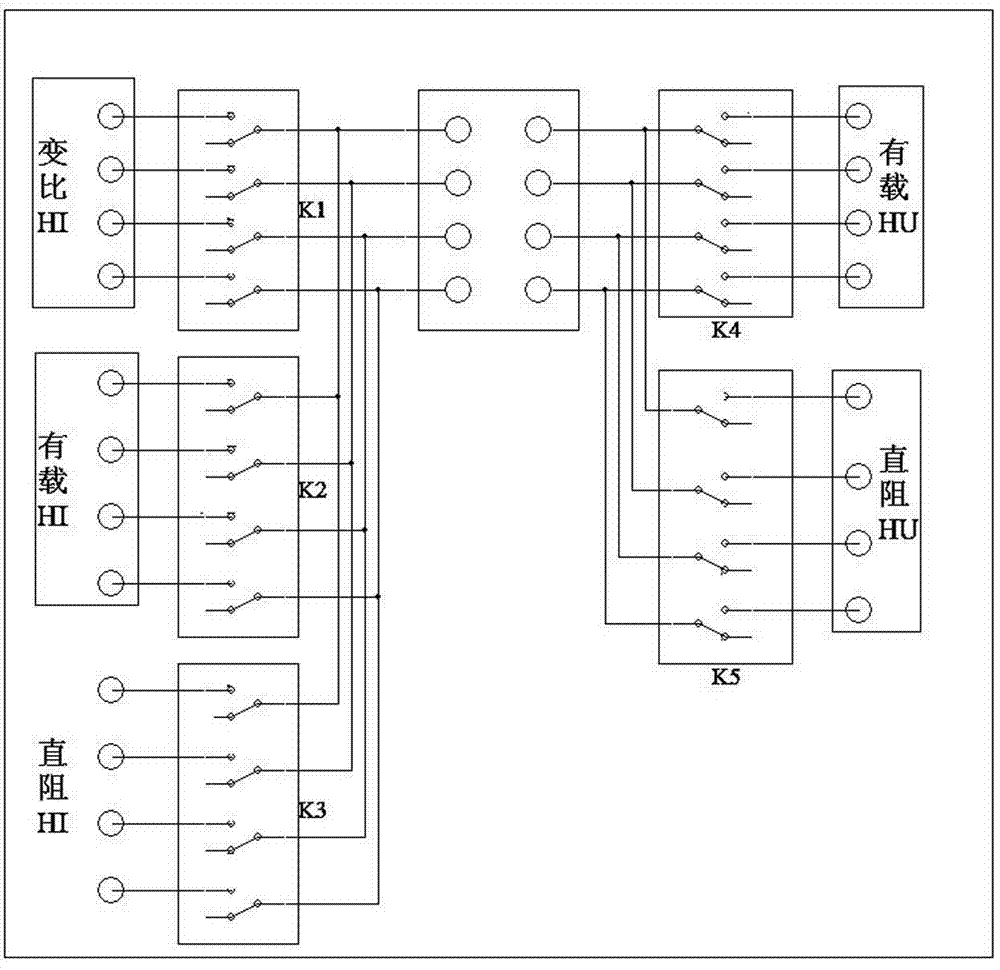
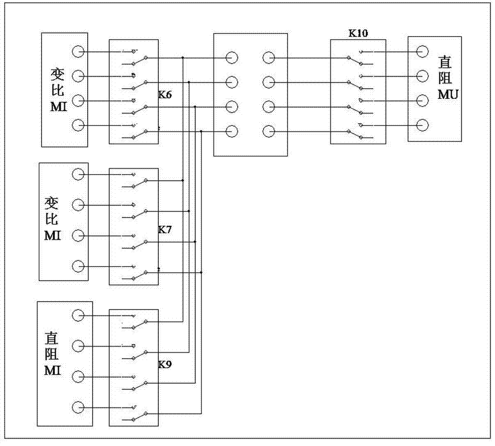
[0016] Such as figure 1 As shown, in this embodiment, the test lines of the three instruments of the electric vehicle-mounted three-phase DC resistance tester, the transformer ratio tester, and the transformer on-load tap-changer tester can be concentrated on the adapter board for unified conversion. The output tester wiring centralized conversion device includes an adapter board, a communication channel selection module set on the adapter board, a CPU control board, a relay control board, an upper computer and a communication interface, and the communication interface selects an analog upper computer through the communication channel The control to select the communication channel is mainly to command the CPU control bo...


PUM


Abstract

The invention relates to a tester wiring concentration conversion device for a vehicle. The tester wiring concentration conversion device for the vehicle comprises an adapter board which is provided with a relay control panel, a central processing unit (CPU) control panel used for controlling the relay control panel, an analog quantity switch communication channel selecting module, an upper computer and a communication interface, wherein the upper computer and the communication interface are used for giving a command control to the CPU control panel. An electrical power vehicle-mounted three phase direct-current resistance tester, a transformer no-load voltage ratio tester and a testing wire of a transformer on-load tap-changer tester are respectively mounted on the adapter board. The communication interface is connected with the analog quantity switch communication channel selecting module which is respectively connected with the upper computer and the CPU control panel. The CPU control panel is further connected with the relay control panel. The analog quantity switch communication channel selecting module selects communication channels through the control of the upper computer. The relay control panel carries out the control command of the CPU and enables the needed relay operation to be achieved, thus reaching the mode of connection and realizing the switchover among the three phase direct-current resistance tester, the transformer no-load voltage ratio tester and the transformer on-load tap-changer tester.

Description

technical field [0001] The invention relates to a centralized conversion device, in particular to a vehicle-mounted three-phase DC resistance, transformation ratio, and on-load comprehensive tester wiring centralized conversion device. Background technique [0002] At present, conventional high-voltage test electric comprehensive test vehicles are generally equipped with transformer DC resistance tester, transformer ratio tester, and transformer on-load tap-changer tester. These three instruments have four sets of test lines Aa, Bb, and Cc respectively. , Oo, the conventional method in the past was to connect the four sets of wires of the instruments to the test object from the four instruments respectively. The three instruments have different lines and different connection methods. The electric power converted in this way There are many wiring on the car, wiring once for a single test item, many times of climbing, high probability of potential safety hazards, many types of...

Claims


Application Information

Patent Timeline
Patent Type & Authority Applications(China)
IPC IPC(8): G01R1/04
Inventor 许扬周志成吉亚民蔡国清刘洋包玉树赵科王静君
Owner STATE GRID JIANGSU ELECTRIC POWER CO ELECTRIC POWER RES INST
Learn More