Exposure machine alignment method and control equipment

A technology for controlling equipment and exposure machines, which is applied to microlithography exposure equipment, originals for photomechanical processing, and exposure devices for photographic plate-making processes. It can solve the problems of reduced production efficiency, low focus definition, and equipment utilization and other problems to achieve the effect of improving the success rate of alignment, improving production efficiency, and avoiding misalignment

Inactive Publication Date: 2013-04-10
BOE TECH GRP CO LTD +1
View PDF7 Cites 13 Cited by
  • Summary
  • Abstract
  • Description
  • Claims
  • Application Information

AI Technical Summary

Problems solved by technology

[0005] However, in the existing alignment method, due to factors such as the limitation of the mask stage structure space, it is impossible to achieve mask mark and work mark alignment
Among them, often because the alignment mark is too much beyond the field of view, the focus definition is too low (that is, the focus score value (Score) is low), which requires manual judgment, and the exposure machine can only be in a temporary waiting state and cannot be carried out normally. exposure
This will affect the utilization rate of equipment and reduce production efficiency

Method used


Image

  • Exposure machine alignment method and control equipment
  • Exposure machine alignment method and control equipment
  • Exposure machine alignment method and control equipment

Examples


Embodiment Construction

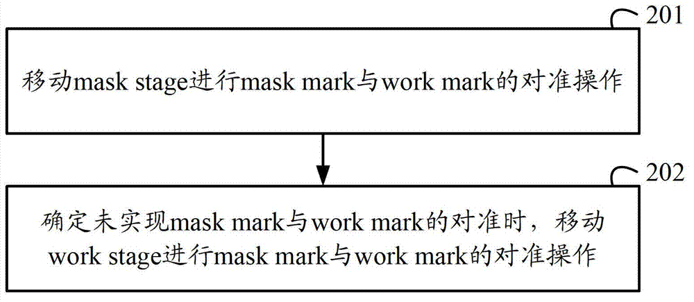
[0024] In order to avoid the misalignment caused by the traditional operation of only moving the abutment carrying the mask to perform alignment mark alignment, improve the success rate of alignment, and improve production efficiency, an embodiment of the present invention provides an exposure machine Counterpoint method.

[0025] Preferred embodiments of the present invention will be described in detail below in conjunction with the accompanying drawings.

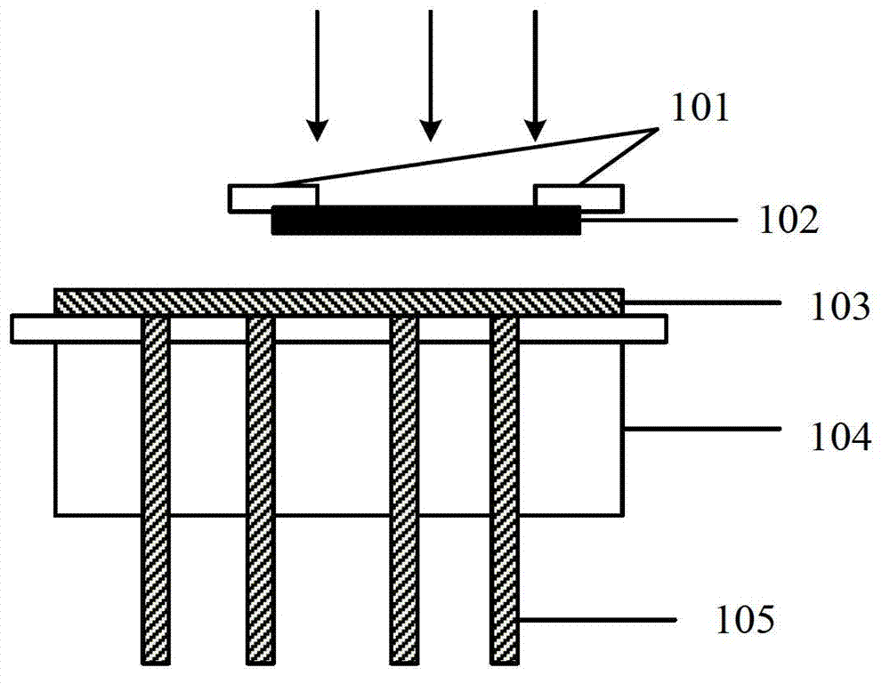
[0026] as attached figure 1 Shown is a schematic diagram of a cross-sectional structure for exposing a substrate, which includes a base (mask stage) 101 for carrying a mask (mask) 102, the mask 102 is adsorbed on the lower surface of the mask stage 101 by vacuum adsorption, and includes a carrying The abutment (work stage) 104 of the substrate (Glass) 103, the Glass 103 is placed on the upper surface of the work stage 104, and also includes a support foot (work pin) 105 for supporting the Glass 103, and the support foot 1...


PUM


Abstract

The invention discloses an exposure machine alignment method, which is used for increasing the alignment success rate and improving the production efficiency. The method comprises the following steps: moving a base platform bearing a photomask and performing alignment operation on an alignment mark of the photomask and an alignment mark of a base plate; and determining to move the base platform bearing the photomask and perform alignment operation on the alignment mark of the photomask and the alignment mark of the base plate when the alignment of the alignment mark of the photomask and the alignment mark of the base plate is not realized. The invention also discloses exposure machine alignment control equipment.

Description

technical field [0001] The invention relates to the technical field of liquid crystal display, in particular to an exposure machine alignment method and control equipment. Background technique [0002] In the process of producing a thin film transistor-liquid crystal display (Thin Film Transistor-Liquid Crystal Display, TFT-LCD), multiple photolithography processes are required. In the photolithography process, the substrate coated with photoresist is exposed by using a mask with a design pattern and ultraviolet light, and the pattern on the mask can be projected onto the photoresist of the substrate, and then developed on the glass substrate. Copy the pattern of the mask. In the production process of TFT-LCD, photolithography needs to be repeated several times to complete the production of the thin film transistor array substrate and the color filter substrate. [0003] Before using the exposure machine for exposure, it is first necessary to carry out the alignment operat...

Claims


Application Information

Patent Timeline
Patent Type & Authority Applications(China)
IPC IPC(8): G03F7/20G03F9/00G03F1/42
Inventor 张鹏飞徐先华张力舟张磊吴琪贾富强刘志
Owner BOE TECH GRP CO LTD
Why Eureka
Try Eureka