Mesh generation method of modeling structural steel knifing pass rolling process

A rolling process and grid generation technology, applied in the pre-processing field of finite element engineering analysis, can solve problems such as rough two-dimensional grid division and unavailable grid division, and achieve the effect of improving stability

Inactive Publication Date: 2013-04-10
ANGANG STEEL CO LTD
View PDF2 Cites 12 Cited by
  • Summary
  • Abstract
  • Description
  • Claims
  • Application Information

AI Technical Summary

Problems solved by technology

This method can effectively obtain the mesh division of the three-dimensional solid, but the two-dimensional mesh division is relatively rough, and it is not mesh division for t

Method used


Image

  • Mesh generation method of modeling structural steel knifing pass rolling process
  • Mesh generation method of modeling structural steel knifing pass rolling process
  • Mesh generation method of modeling structural steel knifing pass rolling process

Examples


Embodiment 1

[0040] See Figure 1 to Figure 5 , is the finite element mesh division of the rolled piece during the rough rolling and deep hole rolling process of the rail:

[0041] 1) First obtain the two-dimensional initial shape of the billet for the required simulation pass, and ensure that the curve is closed;

[0042] 2) Set the seed point on the contour boundary in the two-dimensional plane of the blank. The seed point is dense in the part with large deformation, and one seed point is set every 6mm. The seed point is sparse in the part with small deformation, and one seed point is set every 13mm. In the middle, the transition zone is used to obtain the transition of dense and dense grids, and a seed point is set about every 10mm;

[0043] 3) The grid division in the two-dimensional plane adopts the MSC.Mentat automatic grid calculation method, which generates one unit at a time, and gradually generates a global grid from the boundary of the region to the interior, and the generated ...

Embodiment 2

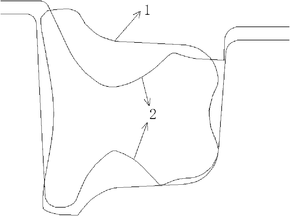
[0047] See Figure 6 ~ Figure 10 , the finite element mesh division of the rolled piece in the process of rough rolling and deep hole cutting of bulbous flat steel:

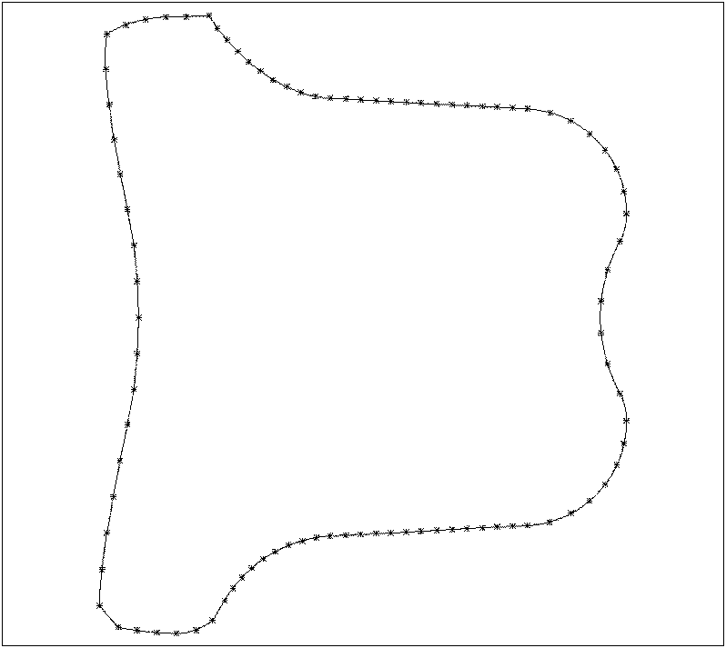
[0048] 1) First obtain the two-dimensional initial shape of the billet for the required simulation pass, and ensure that the curve is closed;

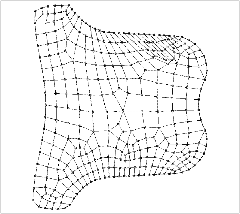
[0049] 2) Set the seed point on the contour boundary in the two-dimensional plane of the blank. The seed point is dense in the part with large deformation, and one seed point is set every 4mm. The seed point is sparse in the part with small deformation, and one seed point is set every 10mm. In the middle of the transition zone to obtain the transition of dense grid, set a seed point about every 7mm;

[0050] 3) The grid division in the two-dimensional plane adopts the MSC.Mentat automatic grid calculation method, which generates one unit at a time, and gradually generates a global grid from the boundary of the region to the inside, and the generated grid is generated based...


PUM


Abstract

The invention relates to the pretreatment field of the finite element engineering analysis, in particular to a mesh generation method of a modeling structural steel knifing pass rolling process. The mesh generation method of the modeling structural steel knifing pass rolling process is characterized by including the steps that (101) seed points are arranged on the outline boundary in the two dimensional plane of the rolled piece with an original shape, (102) mesh generation is proceed in the two dimensional plane to form quadrilateral elements, and (103) the meshes in the two dimensional plane are expanded to form three-dimensional finite element meshes which is the rolled piece model eight nodes hexahedron mesh generation. Compared with the prior art, the mesh generation method of the modeling structural steel knifing pass rolling process has the advantages that three-dimensional finite element meshes produced by the mesh generation method can meet the requirement of structural steel knifing pass rolling process modeling, and finally achieves the aim of modeling knifing pass rolling process accurately and successfully; the rolled piece meshes produced by the generation method can meet the requirement of three-dimensional elastic-plastic heat-machine coupling model analog, ensures enough computational accuracy, and improves stability of calculating.

Description

technical field [0001] The invention relates to the preprocessing field of finite element engineering analysis, in particular to a grid generation method for simulating the process of deep hole cutting and rolling of section steel. Background technique [0002] Due to the particularity of the section steel structure, it is necessary to use deep-cut holes to deform the steel billet unevenly during the rolling production process. The process of billet deformation and stress is complex. In order to accurately understand and master the process, and to accurately control the size and specifications of the rolled piece, it is necessary to use the finite element simulation method. For the simulation of the rail rolling process, due to its complex deformation process, it is necessary to establish a three-dimensional finite element model for simulation, and the rolled piece is divided by a reference unit such as an eight-node hexahedron. Finite element mesh generation is a prerequis...

Claims


Application Information

Patent Timeline
IPC IPC(8): G06F17/50
Inventor 原思宇王军生李广龙高冰赵坦李文斌王旭王奎越费静宋宝宇吴萌
Owner ANGANG STEEL CO LTD
Why Eureka
Try Eureka