Pneumatic contact pin push bending machine

A pin insertion and top bending technology, which is applied in the field of pneumatic pin top bending machines, can solve the problems of affecting product appearance quality, uneven radian, slow processing speed, etc., achieve small error, high shape consistency, and improve production efficiency Effect

Active Publication Date: 2013-04-10
TIANJIN NEW VENTECH ELECTRONICS
View PDF5 Cites 14 Cited by
  • Summary
  • Abstract
  • Description
  • Claims
  • Application Information

AI Technical Summary

Problems solved by technology

This process is completely manual insertion and bending of the guide pins, which has slow processing speed, low production efficiency and poor consistency.
Due...

Method used


Image

  • Pneumatic contact pin push bending machine
  • Pneumatic contact pin push bending machine
  • Pneumatic contact pin push bending machine

Examples


Embodiment Construction

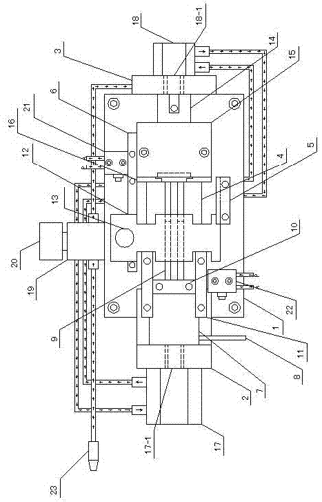
[0017] Below in conjunction with accompanying drawing, the present invention will be further described: with reference to Figure 1 to Figure 10 , a pneumatic pin bending machine includes workbench 1, cylinder A 17, cylinder B 18, cylinder A fixing plate 2, cylinder B fixing plate 3, thimble fixing plate 4, slideway fixing frame 5, slideway supporting frame 6 , thimble push plate 7, push rod 8, thimble plate 9, thimble press plate 10, thimble push plate slider 11, sliding cover plate 12, switch lever 13, looper push plate 14, looper cover plate 15 and skeleton positioning plate 16 ; Cylinder A 17 and cylinder B 18 are respectively fixed on both sides of workbench 1 through cylinder A fixing plate 2 and cylinder B fixing plate 3, and cylinder column A 17-1 and cylinder column B 18-1 are on the same horizontal line, and the thimble pushes Plate 7 is screwed to cylinder column A 17-1.

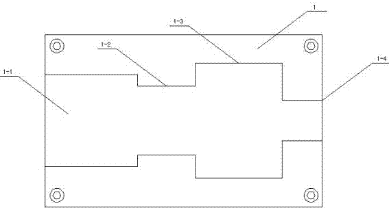
[0018] refer to image 3 , The table of the workbench 1 is respectively provided with a thim...


PUM


Abstract

The invention relates to a pneumatic contact pin push bending machine for production of a transformer. The pneumatic contact pin push bending machine comprises a working platform, two cylinders, a cylinder fixing plate, a thimble fixing plate, a slide fixing frame, a slide supporting frame, a thimble push plate, a push rod, a thimble plate, a thimble pressure plate, a thimble push plate slide block, a sliding cover plate, a switch rod, a curved needle push plate, a curved needle cover plate and a framework locating plate. By using compressed air as power, the cylinders are pushed to operate so that a guide needle is smoothly inserted into a framework guide needle position, and is bent by 100 DEG on the side surface of the framework, and therefore, the whole process of automatically bending a pin is realized during the production of the transformer. The pneumatic contact pin push bending machine has the advantages of high consistency and little errors when being used for processing products, thereby solving the problem that the appearance quality is influenced due to irregular radians on bending ends during manual insertion, reducing the labor intensity of operators, and increasing the production efficiency by about 10 times. Through regulating main parts of different specifications, the pneumatic contact pin push bending machine can adapt to various products and also be applicable to the insertion bending of guide needles of different sizes.

Description

technical field [0001] The invention relates to transformer production and processing equipment, in particular to a pneumatic pin bending machine. Background technique [0002] In the transformer production process, many transformers need to insert the lead pins into the frame, and bend the lead pins at 100 degrees on both sides of the frame. This process relies on manpower to manually insert and bend the guide pins, which has slow processing speed, low production efficiency and poor consistency. Due to manual insertion and bending, the guide pin will have a radian at the bent end, and the radian is uneven, which will affect the appearance quality of the product. Therefore, there is an urgent need to develop a small machine to replace manual operation, which can not only reduce the labor intensity of operators, save human resources, but also improve production efficiency and product consistency. Contents of the invention [0003] In view of the deficiencies in the prior ...

Claims


Application Information

Patent Timeline
IPC IPC(8): H01F41/00H01R43/20H01R43/16
Inventor 李金榜单英孙倩颖赵子旭沈志杰
Owner TIANJIN NEW VENTECH ELECTRONICS
Why Eureka
Try Eureka