Voltage reactive power comprehensive control method of extra-high voltage transformer substation

A voltage reactive power, comprehensive control technology, applied in reactive power compensation, reactive power adjustment/elimination/compensation, etc., can solve the problems of repeated oscillation of the system operating point, limited reactive power voltage regulation capability, and difficulty in reactive power voltage regulation. , to reduce the number of actions, control fast and effective, and ensure the effect of voltage quality

Inactive Publication Date: 2013-04-10
SHANGHAI MUNICIPAL ELECTRIC POWER CO +3
View PDF2 Cites 4 Cited by
  • Summary
  • Abstract
  • Description
  • Claims
  • Application Information

AI Technical Summary

Problems solved by technology

The upper and lower limits of the voltage and reactive power of the traditional control strategy are fixed, and the impact of changes in the operation mode is not considered. In some operation modes, it may be difficult to regulate the reactive power due to the limited reactive power and voltage regulation capacity in the station.
At the same time, this strategy cannot timely adjust the coordination relationship between voltage and reactive power in the process, and it is prone to the problem that the system operating point repeatedly oscillates in the adjacent abnormal area after the voltage regulating device operates

Method used


Image

  • Voltage reactive power comprehensive control method of extra-high voltage transformer substation
  • Voltage reactive power comprehensive control method of extra-high voltage transformer substation

Examples


Embodiment

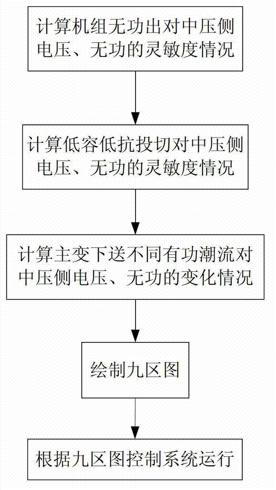
[0046] Such as figure 1 As shown, a comprehensive voltage and reactive power control method for UHV substations, the method controls the voltage and reactive power of substations according to the reactive power output of UHV power grid units near the UHV drop point and the low capacity and low reactance of UHV stations. The control method includes the following steps:

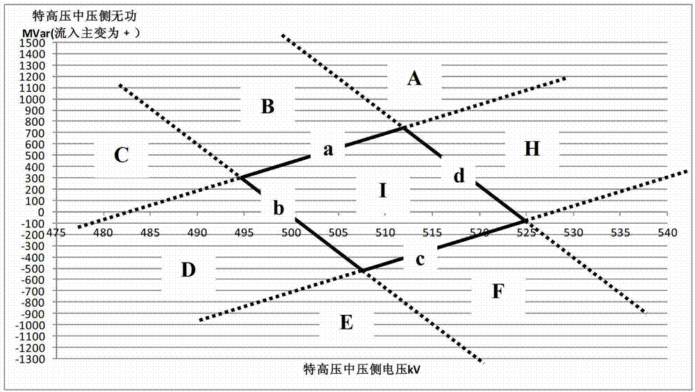
[0047] 1) When the reactive power output of the computer group changes, the changes of UHV medium voltage voltage and reactive power are plotted on the voltage-reactive plane.

[0048] 11) Set the downstream active power flow of the UHV main transformer as 600,000 kilowatts;

[0049] 12) Set the tap position of the UHV main transformer to 1050 / 515 / 110kv;

[0050] 13) Two sets of low reactance are put into the UHV station, and when the reactive power output of the computer group changes from small to large, the voltage and reactive power of the UHV medium voltage side;

[0051] 14) The UHV station does not us...


PUM


Abstract

The invention relates to a voltage reactive power comprehensive control method of an extra-high voltage transformer substation. The process include a first of calculating changing situations of extra-high voltage medium voltage and reactive power when reactive power output changes in a machine group, a second step of calculating changing situations of the extra-high voltage medium voltage and reactive power in the process of switching changes in low capacity and low resistance in the extra-high valve station, a third step of calculating changing situations of the extra-high voltage medium voltage and reactive power when different active power flows are sent downwards by an extra-high main transformer, a fourth step of drawing a voltage reactive power comprehensive control nine-zone diagram according to the calculating results of the first step and the third step, and a fifth step of controlling the system and enabling the system to run in an normal operation area according to the corresponding position of a present operating point in the nine-zone diagram. Compared with the prior art, according to the voltage reactive power comprehensive control method of the extra-high voltage transformer substation, the problems that opposite voltage regulating measures are repeatedly adopted, and the system vibrates in the adjacent area are effectively solved. Operation times of reactive power voltage regulating equipment are reduced, and the voltage reactive power comprehensive control method of the extra-high voltage transformer substation has the advantages of guaranteeing the quality of network voltage and controlling fast and efficiently.

Description

technical field [0001] The invention relates to the field of power systems, in particular to a method for comprehensively controlling voltage and reactive power of an ultra-high voltage substation. Background technique [0002] Due to the large reactive power throughput capacity of UHV AC transmission, the operation mode of the 500kV power grid in the vicinity of its landing point is more complex and changeable, which is bound to have a greater impact on voltage. Voltage is an important indicator to measure power quality. Excessive voltage fluctuations will not only affect the operating life and efficiency of electrical equipment, but also endanger the safe and stable operation of the system. In severe cases, it may even cause voltage collapse and cause large-scale power outages. East China is economically developed, and the power grid has particularly strict requirements on voltage quality. In order to ensure the voltage quality and reactive power balance near the UHV dro...

Claims


Application Information

Patent Timeline
Patent Type & Authority Applications(China)
IPC IPC(8): H02J3/18
CPCY02E40/30
Inventor 黄磊冯煜尧李建华
Owner SHANGHAI MUNICIPAL ELECTRIC POWER CO
Why Eureka
Try Eureka