
Die for radially-oriented sintered NdFeB magnetic ring and production process thereof

A technology of radiation orientation and manufacturing process, applied in the manufacture of inductors/transformers/magnets, electrical components, circuits, etc., it can solve the problems that the number of magnetized magnetic poles cannot be changed at will, thin-walled parts cannot be produced, and the utilization rate of raw materials is low. Achieve stable and reliable product quality, small size and shape restrictions, and high performance consistency

Inactive Publication Date: 2013-04-17
王秋安
View PDF12 Cites 16 Cited by
  • Summary
  • Abstract
  • Description
  • Claims
  • Application Information

AI Technical Summary

Problems solved by technology

[0003] The purpose of the present invention is to solve the problem of the special grain structure and special thermal expansion and contraction performance of the radiation-oriented sintered NdFeB magnetic ring in the prior art, as well as the density inhomogeneity and low yield of the ring during the pressing process. Unstable performance, limited size and shape, thin-walled parts cannot be produced, the number of magnetized poles cannot be changed at will, low utilization rate of raw materials, large processing allowance and low production efficiency, etc. Provide a radiation-oriented sintered NdFeB magnetic ring The mold and its manufacturing process to solve the above problems

Method used


Image

  • Die for radially-oriented sintered NdFeB magnetic ring and production process thereof
  • Die for radially-oriented sintered NdFeB magnetic ring and production process thereof

Examples


Embodiment 1

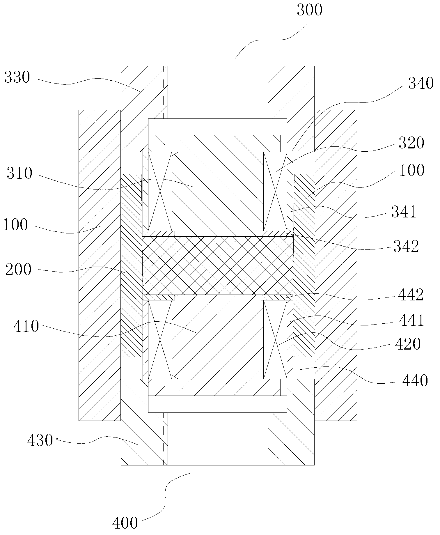
[0029] See figure 1 , A radiation-oriented sintered neodymium iron boron magnetic ring mold, including a magnetically conductive and magnetically concentrated magnetic ring 100, a female mold 200 for accommodating magnetic powder, an upper indenter assembly 300 and a lower indenter assembly 400, The magnetic flux collecting ring 100 and the female mold 200 are annular, the female mold 200 is arranged in the magnetic flux collecting ring 100, the upper indenter assembly 300 and the lower indenter assembly 400 are arranged in the female mold 200 and the upper indenter assembly The pressing surfaces of the upper pressing head assembly 300 and the lower pressing head assembly 400 are arranged opposite to each other, and the pressing surfaces of the upper pressing head assembly 300 and the lower pressing head assembly 400 have the same cross-sectional area as the cavity of the female mold 200. When working in this way, the upper indenter assembly 300 and the lower indenter assembly 4...

Embodiment 2

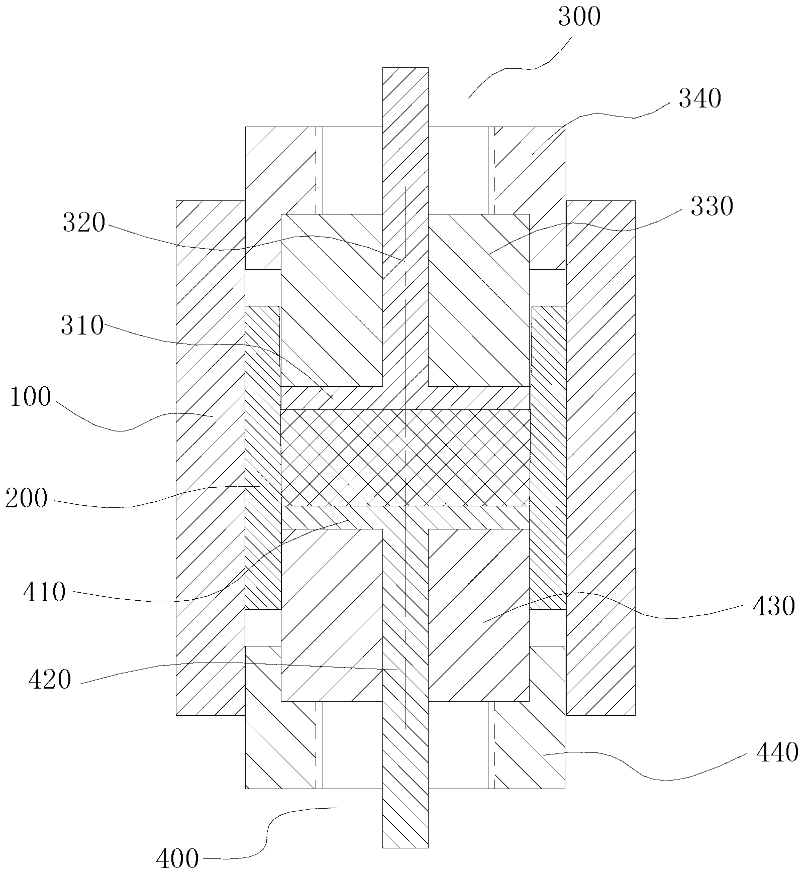
[0045] See figure 2 , A radiation-oriented sintered neodymium iron boron magnetic ring mold, including a magnetically conductive and magnetically concentrated magnetic ring 100, a female mold 200 for accommodating magnetic powder, an upper indenter assembly 300 and a lower indenter assembly 400, The magnetic flux collecting ring 100 and the female mold 200 are annular, the female mold 200 is arranged in the magnetic flux collecting ring 100, the upper indenter assembly 300 and the lower indenter assembly 400 are arranged in the female mold 200 and the upper indenter assembly The pressing surfaces of the upper pressing head assembly 300 and the lower pressing head assembly 400 are arranged opposite to each other, and the pressing surfaces of the upper pressing head assembly 300 and the lower pressing head assembly 400 have the same cross-sectional area as the cavity of the female mold 200. When working in this way, the upper indenter assembly 300 and the lower indenter assembly...


PUM


Abstract

A die for a radially-oriented sintered NdFeB magnetic ring comprises a magnet conducting and gathering ring, a female die, an upper pressure head assembly and a lower pressure head assembly, wherein the female die is arranged in the magnet conducting and gathering ring, the upper and lower pressure head assemblies are arranged in the female die, pressing surfaces of the upper and lower pressure head assemblies are positioned oppositely, and areas of the pressing surfaces of the upper and lower pressure head assemblies are the same with the cross section area of a female die cavity. A production process includes the steps of lifting the upper pressure assembly to the highest position, placing magnetic powder in the female die cavity, pressing the magnetic powder into a magnetic cake, removing a magnetic field, lifting the female die cavity, taking the magnetic cake out, performing isostatic pressing, trepanning and finishing the production process. Materials can be recycled, the utilization rate of the materials is high, the yield of magnetic rings is high, thin-walled parts can be produced, limitation to dimensions and shapes is small, and the amount of magnetized magnetic poles is arbitrary.

Description

Technical field [0001] The invention relates to a mold for a sintered NdFeB magnetic ring and a manufacturing process thereof, in particular to a mold for a radiation-oriented sintered NdFeB magnetic ring and a manufacturing process thereof. Background technique [0002] Radiation-oriented sintered NdFeB magnetic ring has more and more extensive applications in home appliances, automobiles, information, military industry and high technology. However, the existing production technology and process methods have many defects, such as low yield, unstable performance, limited size and shape, thin-walled parts cannot be produced, the number of magnetized magnetic poles cannot be changed at will, and the utilization rate of raw materials is low. , Different defects such as large machining allowance and low production efficiency. The main reason for the above defects is that in the prior art, almost similar production process or production technology is basically used, specifically: fir...

Claims


Application Information

Patent Timeline
Patent Type & Authority Applications(China)
IPC IPC(8): B22F3/03B22F5/00H01F41/02
Inventor 王秋安
Owner 王秋安
Learn More