
Cyclone stripping integration ammonia removal reaction tower

A reaction tower, spiral atomization technology, applied in chemical instruments and methods, water/sewage multi-stage treatment, water/sludge/sewage treatment, etc. The effect of low consumption and convenient operation

Inactive Publication Date: 2013-04-17
NANJING RUNTRY WATER
View PDF10 Cites 15 Cited by
  • Summary
  • Abstract
  • Description
  • Claims
  • Application Information

AI Technical Summary

Problems solved by technology

[0005] However, for the treatment of high-concentration ammonia nitrogen sewage, its treatment efficiency is relatively low
None of the above-mentioned technical solutions can solve the technical problems of high-concentration ammonia-nitrogen sewage treatment well. Therefore, there is an urgent need for a means to solve the above-mentioned technical problems

Method used


Image

  • Cyclone stripping integration ammonia removal reaction tower
  • Cyclone stripping integration ammonia removal reaction tower

Examples


Embodiment 1

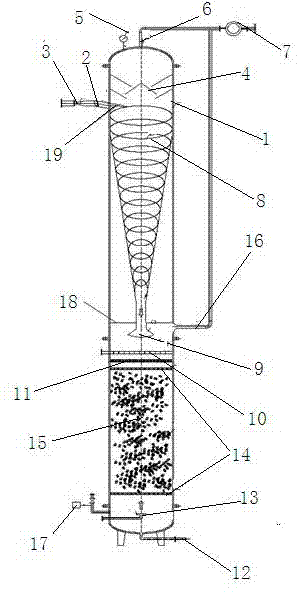
[0021] Example 1: Such as figure 1 Shown is a kind of integrated ammonia removal reaction tower with cyclone blowing off, the reaction tower is a sealed tank body 1 with integral structure, including input device, cyclone separation device, blowing device, detection device and output device; The flow separation device is arranged at the upper end of the tank body 1, and the blow-off device is arranged at the lower end of the tank body 1. The cyclone separation device and the blow-off device are separated by a baffle 18, and the bottom of the cyclone separation device is provided with a water distribution device to control the uniformity of the water outlet. device 9, and the water distributor 9 communicates with the blow-off device. The device has simple structure, convenient operation, low energy consumption and high blowing efficiency.

Embodiment 2

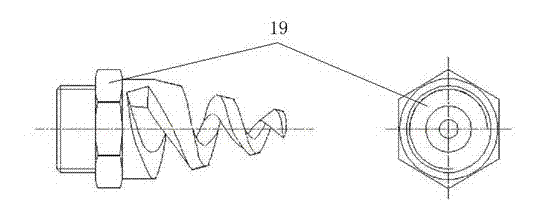
[0022] Example 2: Such as figure 1 , 2 As shown, the input device includes a Venturi tube 3, a water inlet pipe 2, a spiral atomizing nozzle 19 and an air inlet pipe 13, and one end of the water inlet pipe 13 is connected with a Venturi tube 3, and the other end is connected with a spiral atomizing nozzle 19, The spiral atomizing nozzle 19 is installed on the top of the cyclone separation device, and the air inlet pipe 13 is installed at the bottom of the blow-off device; the liquid inlet speed is increased through the Venturi tube 3, and the Venturi tube 3 and the atomizing nozzle 19 work together The lower control liquid enters the state of atomization. The rest of the structures and advantages are exactly the same as in Embodiment 1.

Embodiment 3

[0023] Example 3: Such as figure 1 As shown, the cyclone separation device includes a gas-liquid separator 4 and a diversion groove 8, the gas-liquid separator 4 is installed on the upper part of the spiral atomization nozzle 19, and the flow diversion groove 8 is arranged on the spiral atomization nozzle 19, the bottom of the diversion groove 8 is connected with a water distributor 9, and the diversion groove 8 is set as a conical spiral diversion groove, and the conical spiral diversion groove controls the water to fall in a spiral manner, thereby Prolong the gas-liquid separation time. The rest of the structures and advantages are exactly the same as in Embodiment 1.


PUM


Abstract

The present invention relates to a cyclone stripping integration ammonia removal reaction tower. The reaction tower is a sealing tank of an overall structure, including an input device, a cyclone separation device, a stripping device, a detection device and an output device, wherein the cyclone separation device is disposed on the top of the tank, the stripping device is arranged below the tank, the cyclone separation device and the stripping device are divided by a baffle, and the bottom of the cyclone separation device is provided with a water distributor communicated with the stripping device. The invention employs the way of combining the cyclone separation and the stripping, provides an integration reactor which can remove ammonia efficiently, and has the characteristics of high ammonia removal efficiency, low energy consumption and simple operation.

Description

technical field [0001] The invention relates to the field of sewage treatment devices, in particular to an integrated reaction tower for swirling and stripping ammonia in wastewater. Background technique [0002] High-concentration ammonia-nitrogen wastewater in industrial wastewater has a wide range of sources and a large amount of discharge. In the prior art, steam stripping is mostly used to treat high-concentration nitrogen-containing wastewater. The treatment effect is good, and 70-95% of the ammonia in the wastewater can be stripped out, but This method consumes a lot of energy and is expensive to treat; another commonly used method is the air stripping method, which has low energy consumption and is easy to operate, but it is suitable for wastewater with low ammonia nitrogen concentration, and it is not suitable for wastewater with high concentration. [0003] In view of the above-mentioned technical problems, those skilled in the art are also constantly improving and...

Claims


Application Information

Patent Timeline
IPC IPC(8): C02F9/02
Inventor 李明哲谢小勇王小伟张凯顺王欣
Owner NANJING RUNTRY WATER
Learn More