Box-type postprocessor assembly

A post-processor and assembly technology, applied in the field of auto parts, to achieve the effect of strong noise reduction, low back pressure, and reduced radiation noise

Inactive Publication Date: 2013-04-17
CHINA FIRST AUTOMOBILE
0 Cites 7 Cited by

AI-Extracted Technical Summary

Problems solved by technology

[0005] The technical problem to be solved by the patent of this invention is to integrate the traditional muffle...

Abstract

The invention belongs to the technical field of automobile parts and relates to a box-type postprocessor assembly. The box-type postprocessor assembly comprises a mixed unit, a post-processing unit and a noise reduction unit and is provided with sensors, and each of the mixed unit, the post-processing unit and the noise reduction unit consists of some of end covers, a shell, baffles, sound-absorbing tubes, a post-processing packaging assembly, acoustic boards and an air intake pipe. The box-type postprocessor assembly can be applicable to an SCR (selective catalytic reduction) postprocessor, a transparent POC (particulate organic carbon) filtering postprocessor with a catalyst coating, a DOC (diesel oxidation catalyst) postprocessor and a DPF (diesel particulate filter) postprocessor, enables an engine to meet national IV and national V emission regulations by combining corresponding built-in emission reduction measures, is capable of making effective use of space and is high in conversion efficiency, high in noise reduction capability and low in back pressure.

Application Domain

Technology Topic

Acoustic boardDiesel particulate filter +6

Image

  • Box-type postprocessor assembly
  • Box-type postprocessor assembly
  • Box-type postprocessor assembly

Examples

  • Experimental program(1)

Example Embodiment

[0028] specific implementation plan
[0029] Taking the selective catalytic reduction post-processor as an example, the structural design and manufacturing process of the assembly will be described in detail below.
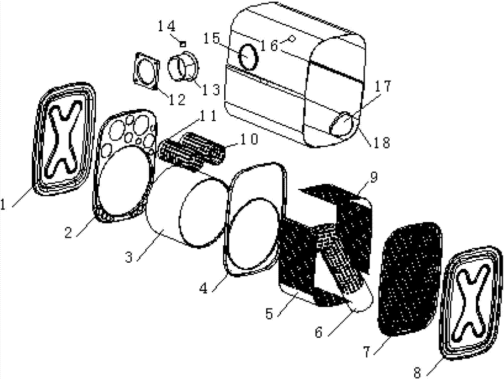
[0030] The device of the present invention that can reduce engine exhaust pollutants and exhaust noise has a box-like shape, a flange connection to the air inlet, a temperature sensor 14, and a nitrogen-oxygen sensor 16 behind the post-processing unit. .
[0031] The device of the present invention that can reduce engine exhaust pollutants and exhaust noise includes a mixing unit, a post-processing unit, and a noise reduction unit. noise effect.
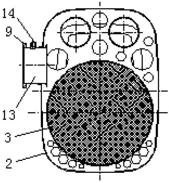
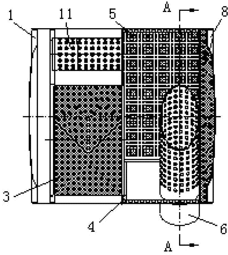
[0032] like figure 1 As shown, the mixing unit in the present invention is formed by the intake pipe 13, the shell 18, the partition I2, the partition II4, the aftertreatment package assembly 3, the sound absorption pipe I10, the sound absorption pipe II11, the left end cover 1 and the right end cover 8 The post-processing unit is formed by encapsulating the carrier in a stainless steel shell 18; the noise reduction unit consists of a partition II4, a post-processing package assembly 3, a shell 18, a sound-absorbing board I5, a sound-absorbing board III9, a sound-absorbing board II7, an exhaust A tube 6, a left end cap 1 and a right end cap 8 are formed.
[0033] First package the post-processing assembly 3, partition I2, partition II4, sound-absorbing tube I10 and sound-absorbing tube II11 such as figure 1 Weld to form the partition assembly, and press the partition assembly into the designated position of the housing 18 before welding; then insert the air intake pipe 13 from the air intake pipe hole 15 of the housing 18 to the designated position and weld it, and weld it on the air intake pipe 13 Flange 12, and temperature sensor 14;
[0034] Then sound-absorbing board I5 and sound-absorbing board III9 are installed with sound-absorbing material, welded to the specified position of the shell 18, and one end of the exhaust pipe 6 is welded to the sound-absorbing board I5, and the other end of the exhaust pipe 6 (open end ) through the exhaust pipe hole 17 of the shell 18 and welded; then the sound-absorbing plate II7 is pressed into the specified position in the shell 18 and then welded, and the sound-absorbing material is added at the same time, and finally the left end cover 1 and the right end cover 8 are connected to the shell 18 Both ends are welded to form a box-type afterprocessor assembly.

PUM

no PUM

Description & Claims & Application Information

We can also present the details of the Description, Claims and Application information to help users get a comprehensive understanding of the technical details of the patent, such as background art, summary of invention, brief description of drawings, description of embodiments, and other original content. On the other hand, users can also determine the specific scope of protection of the technology through the list of claims; as well as understand the changes in the life cycle of the technology with the presentation of the patent timeline. Login to view more.

Similar technology patents

Transmission control protocol method for satellite network

InactiveCN101854738AIncrease profitReduce the likelihood of discardingNetwork topologiesWireless network protocolsData transmissionUtilization factor
Owner:NANJING UNIV OF POSTS & TELECOMM

Classification and recommendation of technical efficacy words

  • Improve conversion efficiency
  • Increase profit

System and Method for Color Mixing Lens Array

InactiveUS20120068615A1Heating is therefore reduced and preventedImprove conversion efficiencyPlanar light sourcesLight source combinationsColor mixingLight beam
Owner:ILLUMITEX INC

Light-scattering film and optical device using the same

InactiveUS20060137735A1Improve conversion efficiencyPV power plantsDiffusing elementsElectrical resistivity and conductivityConductive materials
Owner:MITSUBISHI HEAVY IND LTD

Quantum dot film and backlight module

InactiveCN103487857AIncrease profitImprove light conversion efficiencyDiffusing elementsNon-linear opticsOptical pathMultiple quantum
Owner:ZHANGJIAGANG KANGDE XIN OPTRONICS MATERIAL

Software-defined network controller supporting scheduling of dynamic elastic resource

ActiveCN103338163AIncrease profitAchieving Dynamic ResilienceData switching networksVirtualizationSoftware-defined networking
Owner:TSINGHUA UNIV
Why Eureka
Try Eureka