Surface ash clearing device of pipe heat exchanger

A technology of tubular heat exchanger and cleaning device, which is applied in the direction of cleaning heat transfer devices, non-rotating equipment cleaning, lighting and heating equipment, etc., which can solve the problems of increased flue gas humidity, high maintenance costs, and dust accumulation, and achieves convenience clear effect

Inactive Publication Date: 2013-04-17
CHENGXIN GREEN INTEGRATION
View PDF5 Cites 5 Cited by
  • Summary
  • Abstract
  • Description
  • Claims
  • Application Information

AI Technical Summary

Problems solved by technology

Both of these two sootblowing methods can remove soot deposits to a certain extent, but due to structural characteristics, steam soot blowing will increase the humidity of the flue gas, which is more likely to cause soot deposits, poor operational reliability, high equipment failure rate, and high maintenance costs; The soot blowing effect of the sonic soot blower is not obvious, and the investment and maintenance costs are relatively high

Method used


Image

  • Surface ash clearing device of pipe heat exchanger

Examples


Embodiment Construction

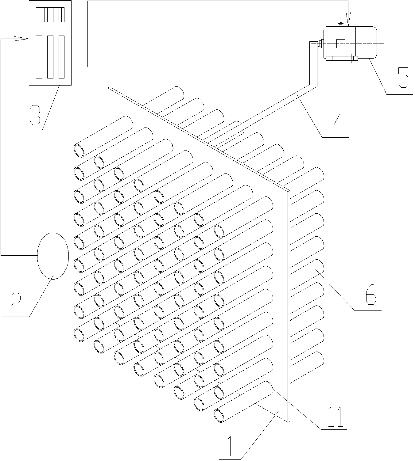
[0011] Such as figure 1 As shown, the device for removing dust on the surface of the tubular heat exchanger of the present invention includes a heat exchanger tube bundle arranged in the flue, a dust removal orifice plate 1, a driving connecting rod 4, a smoke resistance sensor 2, a motor 5 and a controller 3. The dust removal orifice 1 is provided with a plurality of through holes 11 and penetrates into the outer rings of the heat exchange tubes 6 of the heat exchanger tube bundle respectively. The output end of the controller 3 is connected to the control signal input end of the motor 5 , the smoke resistance sensor 2 is arranged in the flue and the signal output end is connected to the signal input end of the controller 3 .

[0012] Furthermore, the diameters of the several through holes 11 of the dust removal orifice plate 1 are larger than the outer diameter of the heat exchange tube 6 . The diameter of several through holes of the dust removal orifice is larger than the...


PUM


Abstract

The invention discloses a surface ash clearing device of a pipe heat exchanger. The clearing device comprises a heat exchanger pipe bundle arranged in a smoke channel, a dust-removing hole plate, a driving connection rod, a smoke resistance sensor, a motor and a controller. The dust-removing hole plate is provided with a plurality of through holes, a heat exchanger pipe outer ring of the heat exchanger pipe bundle respectively penetrates through the through holes, two ends of the driving connection rod are respectively connected with the dust-removing hole plate and a motor rotating shaft, the output end of the controller is connected with the control signal input end of the motor, the smoke resistance sensor is arranged in the smoke channel, and the signal output end is connected with the signal input end of the controller. The clearing device is capable of effectively and conveniently clearing surface ash of heat exchanger pipes, avoids the shortcoming of a traditional ash blowing mode, and ensures stable and economical operation of a boiler.

Description

technical field [0001] The invention relates to a device for removing dust accumulated on the surface of a tubular heat exchanger. Background technique [0002] Tube heat exchangers are mostly used in the tail flue of the boiler to exchange heat for the flue gas, and collect the waste heat of the flue gas for reuse. When the flue gas in the tail flue of the boiler scours the tube bundle of the heat exchanger, a vortex zone is formed on the leeward side of the tube, and the ash particles with large particle size are not easily drawn into the vortex zone because of their high kinetic energy; With strong adsorption force, it is easy to be drawn into the vortex and hit the pipe wall to form dust accumulation. Fly ash accumulated on the surface of heat exchanger tubes with low flue temperature at the tail of the boiler is generally dry and loose, which belongs to loose ash accumulation. [0003] Ash accumulation leads to increased heat transfer resistance, lower heat transfer c...

Claims


Application Information

Patent Timeline
Patent Type & Authority Applications(China)
IPC IPC(8): F28G1/08
Inventor 王金旺张燕刘雷陈
Owner CHENGXIN GREEN INTEGRATION
Why Eureka
Try Eureka