Fixing device for acoustic emission sensor used in rock triaxial test under confining pressure condition

A technology of acoustic emission sensor and three-axis experiment, which is applied in the direction of measuring devices, instruments, scientific instruments, etc., can solve the problems of acoustic emission sensor detachment, signal interference, and signal interference information, etc., so as to accurately locate the location of rock sample rupture , prevent damage and destruction, reduce the effect of interference signals

Active Publication Date: 2013-04-17
CHINA UNIV OF MINING & TECH
View PDF5 Cites 24 Cited by
  • Summary
  • Abstract
  • Description
  • Claims
  • Application Information

AI Technical Summary

Problems solved by technology

In rock uniaxial compression acoustic emission monitoring, the acoustic emission sensor is usually directly fixed on the rock surface by rubber band or adhesive tape. The contact area of ​​the sample is very small, and when the deformation of the rock sample is large, the acoustic emission sensor is often separated from the rock sample, resulting in the failure of the experiment; in the rock compression acoustic emission monitoring experiment under confining pressure, due to the ceramic At present, there are two main ways to arrange the acoustic emission sensor: one is to arrange the acoustic emission sensor on the outer wall of the loading cylinder. Due to too many influencing factors, such as the in...

Method used


Image

  • Fixing device for acoustic emission sensor used in rock triaxial test under confining pressure condition
  • Fixing device for acoustic emission sensor used in rock triaxial test under confining pressure condition
  • Fixing device for acoustic emission sensor used in rock triaxial test under confining pressure condition

Examples


Embodiment Construction

[0016] An embodiment of the present invention will be further described below in conjunction with the accompanying drawings:

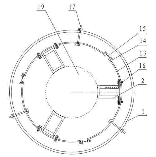
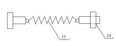
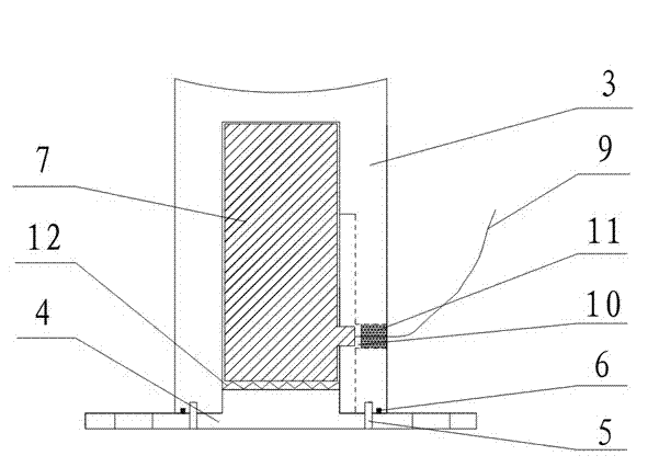
[0017] figure 1 As shown, the acoustic emission sensor fixing device for rock triaxial experiment under confining pressure of the present invention is mainly composed of a fixed ring 1, a plurality of acoustic emission sensor sealing chambers 2 and a pre-tensioning mechanism. The pre-tensioning mechanism includes a plurality of arc-shaped pre-tensioning steel sheets 13 and an adjusting bolt 14 connecting the plurality of arc-shaped pre-tensioning steel sheets 13 into a circular ring. In connection, the length of the spring 15 can be adjusted by the adjusting bolt 14 connected to the spring 15. The acoustic emission sensor sealing chamber 2 is fixed to the arc-shaped pre-tightening steel sheet 13 through the screw holes on the sealing cover. The adjusting bolt 14 is used to adjust the length of the spring 15 so that the acoustic emission sensor sealing cha...


PUM


Abstract

A fixing device for an acoustic emission sensor used in a rock triaxial test under the confining pressure condition is suitable for an indoor acoustic emission test on the rock damage mechanism, damage positioning and accumulation process in conventional rock triaxial and uniaxial compression tests. The fixing device comprises a fixing ring, a pretensioning mechanism and an acoustic emission sensor sealed chamber, wherein the fixing ring is hinged with the pretensioning mechanism through bolts; the acoustic emission sensor sealed chamber comprises a sealed cylinder body with a guide groove and acoustic emission sensors arranged in the sealed cylinder body, and a wire outlet into which a bonding steel structured glue is injected is formed in the side wall of the sealed cylinder body; and the pretensioning mechanism comprises springs and adjusting bolts, through which a plurality of arc-shaped pretensioning steel sheets are connected into a circular ring. The fixing device can effectively protect the acoustic emission sensors and prevent the acoustic emission sensors from damage and destroy under high oil pressure without influencing original measurement equipment, ensures that an acoustic emission monitoring system is always in close contact with a rock sample, remarkably reduces interference signals in the acoustic emission test, and satisfies the acoustic emission test requirement in the rock material damage process.

Description

Technical field [0001] The invention relates to an acoustic emission sensor fixing device for rock triaxial experiments under confining pressure conditions, and is particularly suitable for experiments that require the use of acoustic emission signals to locate rock sample fracture positions. Background technique [0002] As a special engineering medium, rock materials will experience complex stress loading and unloading effects in various geotechnical engineering. When the external force reaches a certain limit, new cracks will be generated inside the rock. With the loading of the external force, these new cracks The original cracks in the rock and the rock will expand and penetrate, which will cause geotechnical engineering geological disasters. Therefore, studying the fracture process of rock under stress is of great significance for understanding the failure mechanism of geotechnical engineering and guiding construction design. [0003] In the process of rock rupture, the stra...

Claims


Application Information

Patent Timeline
IPC IPC(8): G01N3/02
Inventor 张凯张后全吴宇
Owner CHINA UNIV OF MINING & TECH
Why Eureka
Try Eureka