
Modular primary permanent magnetic linear motor and motor module consisting of same

A permanent magnet linear motor, modular technology, applied in the direction of electric components, electrical components, electromechanical devices, etc., can solve the problems of increased system manufacturing costs and maintenance costs, high costs of permanent magnets and armatures, and achieve simple structure and easy heat dissipation. , the effect of high power density

Active Publication Date: 2013-04-17
SOUTHEAST UNIV
View PDF3 Cites 25 Cited by
  • Summary
  • Abstract
  • Description
  • Claims
  • Application Information

AI Technical Summary

Problems solved by technology

However, since the permanent magnets and armature windings of traditional permanent magnet motors are installed in the primary and secondary respectively, and the cost of both permanent magnets and armatures is high, it will undoubtedly lead to system failure in long secondary applications such as rail transit. Substantial increase in manufacturing and maintenance costs

Method used


Image

  • Modular primary permanent magnetic linear motor and motor module consisting of same
  • Modular primary permanent magnetic linear motor and motor module consisting of same
  • Modular primary permanent magnetic linear motor and motor module consisting of same

Examples


Embodiment 1

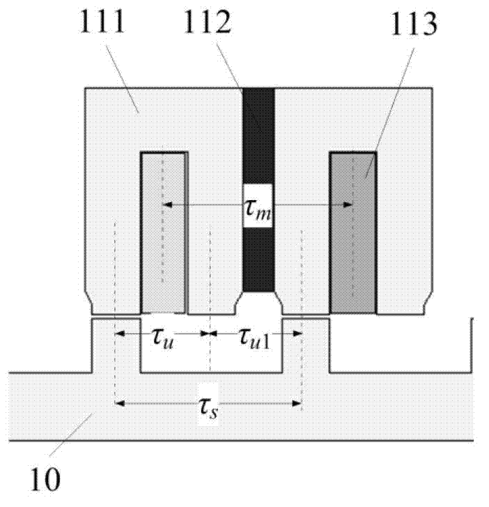
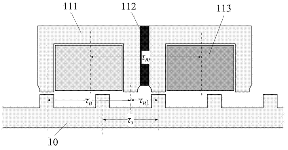
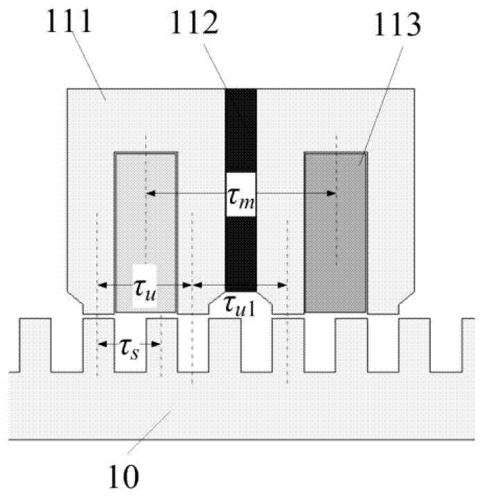
[0032] The present invention includes a primary 11, a secondary 10 and a concentrated winding 113, wherein both the primary 11 and the secondary 10 are salient pole structures with an air gap between them.

[0033] The primary 11 includes m or 2m primary modules (110), where m is the phase number of the motor; a magnetically permeable or non-magnetically permeable material 114 is filled between two adjacent primary modules (110).

[0034] Each primary module 110 includes two U-shaped magnetically permeable materials 111 and a permanent magnet 112 disposed between the U-shaped magnetically permeable materials 111 . The concentrated winding 113 is disposed in the slot of the primary module 110 and covers the permanent magnet 112 .

[0035] The distance between the central axes of the two teeth of each U-shaped magnetically permeable material 111 is τ u , the distance between the central axes of the two U-shaped magnetic permeable materials 111 teeth on both sides of the permanen...

Embodiment 2

[0052] Such as Figure 6 and 7 As shown, the difference between the modularized primary permanent magnet linear motor in this embodiment and that in Embodiment 1 is that the relative displacement between the two primary modules 110 belonging to the same phase satisfies λ 1 =nτ s ,exist Figure 6 where n=19, in Figure 7 where n=6, so the two primary modules 110 belonging to the same phase do not have complementary characteristics. also in Figure 6 The two primary modules 110 belonging to the same phase are placed adjacent to each other, while in Figure 7 Two primary modules 110 belonging to adjacent phases are placed together. Therefore, for the sake of illustration, Figure 6 The structure in is called "ABCABC", Figure 7 The structure in is called "2A2B2C". Theoretically, in order to obtain an m-phase motor, the relative displacement between two primary modules 110 belonging to different phases needs to satisfy λ 2 =(i±1 / m)τ s or lambda 2 =[i±(0.5-1 / m)]τ s Tha...


PUM


Abstract

The invention discloses a modular primary permanent magnetic linear motor and a motor module consisting of the modular primary permanent magnetic linear motor. The modular primary permanent magnetic linear motor comprises a primary and a secondary, wherein the primary comprises m or 2m primary modules; each primary module comprises two U-shaped magneto-conducting materials and a permanent magnet between the U-shaped magneto-conducting materials; and taum, taus, tauul, tauu, wmt and wst satisfy the following relational expressions that tm is equal to or approximate to ktaus, tauul is equal to or approximate to (j+0.5) taus, tauul is equal to taum-tauul, and wmt is less than or equal to wst. Relative displacement between two primary modules which belong to the same phase is lambda1 which is equal to (n+ / -0.5)taus or lambda1 which is equal to ntaus, and relative displacement between two primary modules which belong to different phases is lambda2 which is equal to (i+ / -1 / m)taus or lambda2 which is equal to [i+ / -(0.5-1 / m)]taus. The motor and the motor module have the advantages of symmetric counter potential, relatively low sine and positioning force, small thrust ripple and the like, and are applied to the places where a long secondary structure linear motor is applied.

Description

technical field [0001] The invention relates to a modularized primary permanent magnet linear motor and a motor module composed of it, belonging to the technical field of motor manufacturing. Background technique [0002] With the development of industry, linear motors are widely used. Compared with the traditional rotary motor drive method, the use of linear motor drive eliminates the need for mechanical gears that convert rotary motion into linear motion, which can reduce costs, reduce noise, reduce system volume, and reduce maintenance costs. Especially in rail transit applications, when a rotating motor is used to drive, the driving force is generated by the adhesion between the wheel and the rail. When the speed is too high or deceleration, there will be problems such as wheel-rail slippage. Therefore, the technical means of replacing the rotary motor with a linear motor can overcome the above-mentioned shortcomings of the rotary motor in this application and improve t...

Claims


Application Information

Patent Timeline
Patent Type & Authority Applications(China)
IPC IPC(8): H02K41/03
Inventor 程明曹瑞武花为王欣
Owner SOUTHEAST UNIV
Learn More