Synchronous triggering system in distributed type measurement

A synchronous triggering and distributed technology, applied in the field of signal detection, can solve the problems of low synchronization accuracy, large wiring workload, limited application scope, etc., and achieve the effect of ingenious design and reasonable structure.

Inactive Publication Date: 2013-04-17
ZHONGBEI UNIV
View PDF2 Cites 4 Cited by
  • Summary
  • Abstract
  • Description
  • Claims
  • Application Information

AI Technical Summary

Problems solved by technology

[0003] The present invention provides a synchronous trigger system in distributed measurement in order to solve the problems of the existing synchronous trigg

Method used


Image

  • Synchronous triggering system in distributed type measurement
  • Synchronous triggering system in distributed type measurement
  • Synchronous triggering system in distributed type measurement

Examples


Example Embodiment

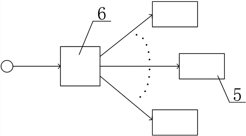
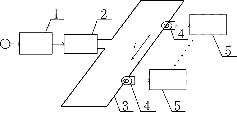
[0012] Synchronous trigger system in distributed measurement, including S / V signal conversion circuit 1, numerical control current switch 2, current loop 3, induction trigger module 4, and distributed measurement node 5; signal output of S / V signal conversion circuit 1 The terminal is connected to the signal input terminal of the digital control current switch 2; the digital control current switch 2 and the induction trigger module 4 are both connected in series on the current loop 3; the signal output terminal of the induction trigger module 4 and the trigger signal input terminal of the distributed measurement node 5 connection;

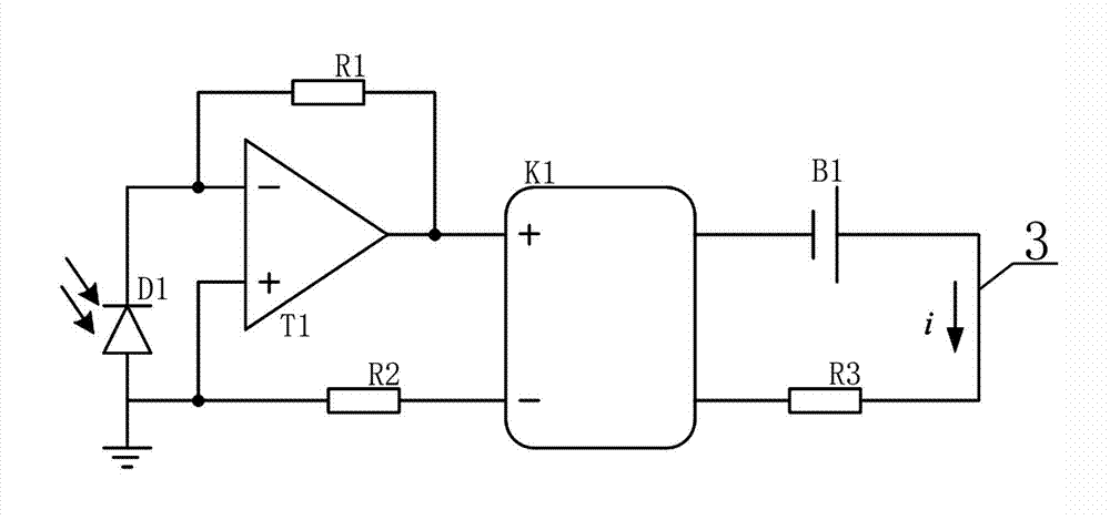
[0013] The S / V signal conversion circuit 1 includes a photodiode D1, an operational amplifier T1, and first-second resistors R1-R2; the digitally controlled current switch 2 includes a solid state relay K1, a battery B1, and a third resistor R3; The positive input of amplifier T1 and the anode of photodiode D1 are both grounded; the negative input of ...


PUM


Abstract

The invention relates to a signal detection technology, in particular to a synchronous triggering system in distributed type measurement. The synchronous triggering system solves the problems of complex circuit, large wire-distributing workload, poor flexibility of measuring-node distribution, low synchronization accuracy and limited application range in the existing synchronous triggering system. The synchronous triggering system comprises an S/V signal conversion circuit, a numerical control current switch, a current loop, an induction triggering module and distributed type measuring nodes, wherein the signal output end of the S/V signal conversion circuit is connected with the signal input end of the numerical control current switch; the numerical control current switch and the induction triggering module are respectively connected on the current loop in series; and the signal output end of the induction triggering module is connected with the triggering signal input ends of the distributed type measuring nodes. The synchronous triggering system is applicable to transient signal measurement.

Description

technical field [0001] The invention relates to signal detection technology, in particular to a synchronous trigger system in distributed measurement. Background technique [0002] The distributed measurement system is usually composed of multiple independent distributed measurement nodes, and the location of each distributed measurement node is flexible, so it is especially suitable for transient signal measurement in the field (such as transient pressure measurement, transient temperature measurement, Transient vibration measurement, etc.). In the process of transient signal measurement using a distributed measurement system, the time when the signal arrives at each distributed measurement node is often different, and the time difference of the signal arriving at each distributed measurement node can be used to analyze the propagation characteristics and field distribution characteristics of the signal. However, in the existing distributed measurement system, multiple dis...

Claims


Application Information

Patent Timeline
IPC IPC(8): H03K17/90H03K17/945
Inventor 王文廉王玉赖富文张志杰
Owner ZHONGBEI UNIV
Why Eureka
Try Eureka