Fixture structure for machining inner cavities and joint closing surfaces of glass molds

A technology of glass molds and joint surfaces, applied in the field of tooling and fixtures, can solve the problems of difficult manufacturing, affecting the processing efficiency of machining centers, and high failure rates, and achieve the effects of easy use and maintenance, improved processing efficiency, and reduced operating intensity

Active Publication Date: 2013-04-24
ORI MOLD TECH SUZHOU
View PDF15 Cites 43 Cited by
  • Summary
  • Abstract
  • Description
  • Claims
  • Application Information

AI Technical Summary

Problems solved by technology

[0005] Typical such as CN102380777B, CN102350650B and CN102423859B disclosed respectively "clamp device for glass mold processing", "clamp device for glass mold processing" and "clamp device for glass mold processing". Reliable clamping under the condition that the mold cavity faces upwards, so that the joint surface and the mold cavity can be processed by a machining center such as a CNC machine tool, but the three patent solutions have the following shortcomings: First, due to the need to pass through a pair of horizontal The adjustment mechanism contacts the surface of both sides of the glass mold in the length direction to adjust the horizontal state of the glass mold, and because it is necessary to manually operate the clamp drive mechanism, the clamp drive mechanism drives a pair of clamps (the patent is called the first clamp and the second clamp), a pair of clamp clamps the two ends of the glass mold until a pair of pressure plates press the two ends of the glass mold, so the overall structure is very complicated, not only difficult to manufacture, but also easy to use and Maintenance is troublesome. In addition, the probability of failure is relatively high; secondly, due to the lack of reasonable mold lifting function, the labor intensity of the operator is increased due to the inconvenience of grasping and pinching each time the mold is loaded and unloaded; thirdly, because a set of mechanisms only It is suitable for clamping one half of a pair of glass molds (a pair of glass molds is composed of two matched half molds), so the number of clamping times is large, which affects the processing efficiency of the machining center, especially if the same pair is a set The two halves of the glass mold are divided into two clamps, which will affect the accuracy (fitting accuracy) of the entire glass mold

Method used


Image

  • Fixture structure for machining inner cavities and joint closing surfaces of glass molds

Examples


Embodiment Construction

[0020] In order to enable the examiners of the patent office, especially the public, to understand the technical essence and beneficial effects of the present invention more clearly, the applicant will describe in detail the following in the form of examples, but none of the descriptions to the examples is an explanation of the solutions of the present invention. Any equivalent transformation made according to the concept of the present invention which is merely formal but not substantive shall be regarded as the scope of the technical solution of the present invention.

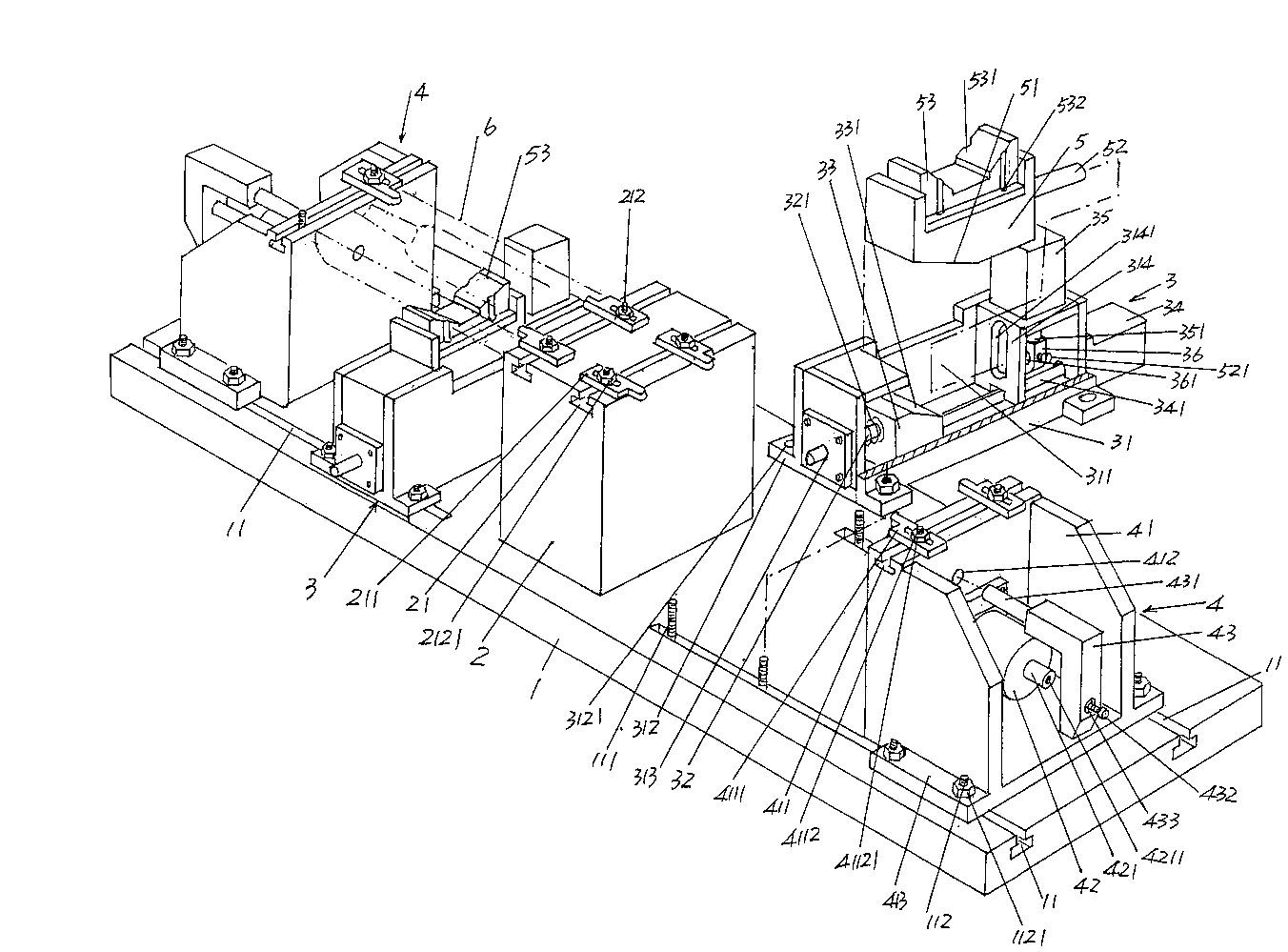
[0021] Please see figure 1 , a base plate 1 is given, and a pair of adjustment slots 11 parallel to each other are opened at one end (the left end of the position state shown in the figure) and the other end (the right end of the position state shown in the figure) of the base plate 1, as shown in the figure The adjustment groove 11 is provided on the upward side of the base plate 1 in use, and the cross-sect...


PUM


Abstract

A fixture structure for machining inner cavities and joint closing surfaces of glass molds comprises a bottom seat plate, a center frame, two automatic mold supporting guide block lifting mechanisms and two automatic glass mold end surface locking mechanisms. Adjusting grooves are respectively arranged on surfaces of two ends of the bottom seat plate; adjusting grooves of mold pressing plates of the center frame are arranged on the top surface of the center frame, and the mold pressing plates of the center frame are respectively fittingly arranged on the adjusting grooves of the mold pressing plates of the center frame; the two automatic mold supporting guide block lifting mechanisms and the two automatic glass mold end surface locking mechanisms are respectively arranged at the two ends of the bottom seat plate, the automatic mold supporting guide block lifting mechanisms are positioned among the center frame and the automatic glass mold end surface locking mechanisms, a mold supporting guide block is arranged on the automatic mold supporting guide block lifting mechanism positioned at one end of the bottom seat plate, and another mold supporting guide block is arranged on the automatic mold supporting guide block lifting mechanism positioned at the other end of the bottom seat plate. The fixture structure has the advantages that the fixture structure is simple, and is convenient to manufacture and easy to use and maintain; the operation intensity is relieved for operators; loosening is prevented; and the machining efficiency of a machining center is improved, and the perfect matching precision between two half molds of a mold can be guaranteed.

Description

technical field [0001] The invention belongs to the technical field of fixtures, and in particular relates to a fixture structure for processing the inner cavity and seam surface of a glass mold. Background technique [0002] Fixtures play a very important role in the production of industrial products, and the processing of glass molds is no exception. The so-called tooling fixture refers to special equipment or tools used to clamp or position workpieces in machining to meet certain process requirements. Fixtures usually need to meet the requirements of no interference during product production, accurate and reliable positioning, and convenient operation. Since the tooling fixture has the exclusive characteristics of manufacturing a certain product, the degree of generalization is low, and it is often made by the manufacturer of the product. Glass mold manufacturers are also mostly equipped with various tooling fixtures in a self-made way. In recent years, although all kin...

Claims


Application Information

Patent Timeline
Patent Type & Authority Applications(China)
IPC IPC(8): B23Q3/08
Inventor 戈剑鸣
Owner ORI MOLD TECH SUZHOU
Why Eureka
Try Eureka