Electromagnetic brake

An electromagnetic brake and brake plate technology, applied in the direction of the hoisting device, etc., can solve the problems such as the inability to unilaterally adjust the contact between the brake pad and the rotor, the automatic adjustment of the friction angle, and the asymmetric wear of the brake pad, so as to achieve a novel appearance and improve production. Efficiency and easy air gap adjustment

Active Publication Date: 2015-02-25
浙江西子富沃德电机有限公司
View PDF9 Cites 4 Cited by
  • Summary
  • Abstract
  • Description
  • Claims
  • Application Information

AI Technical Summary

Problems solved by technology

[0003] During the daily power-on and power-off operation of the brake, the brake pads are eccentrically worn due to rotor runout, bearing precision, and manufacturing precision. The traditional structure cannot unilaterally adjust the contact between the brake pads and the rotor.
[0004] The brake pad wear caused by the brake pad lock process often shows asymmetric wear. The current fastening method of the brake pad assembly and the armature cannot automatically adjust the friction angle during the friction process between the brake pad and the brake wheel, resulting in eccentric wear. Causes uneven brake air gap

Method used


Image

  • Electromagnetic brake
  • Electromagnetic brake
  • Electromagnetic brake

Examples


Embodiment Construction

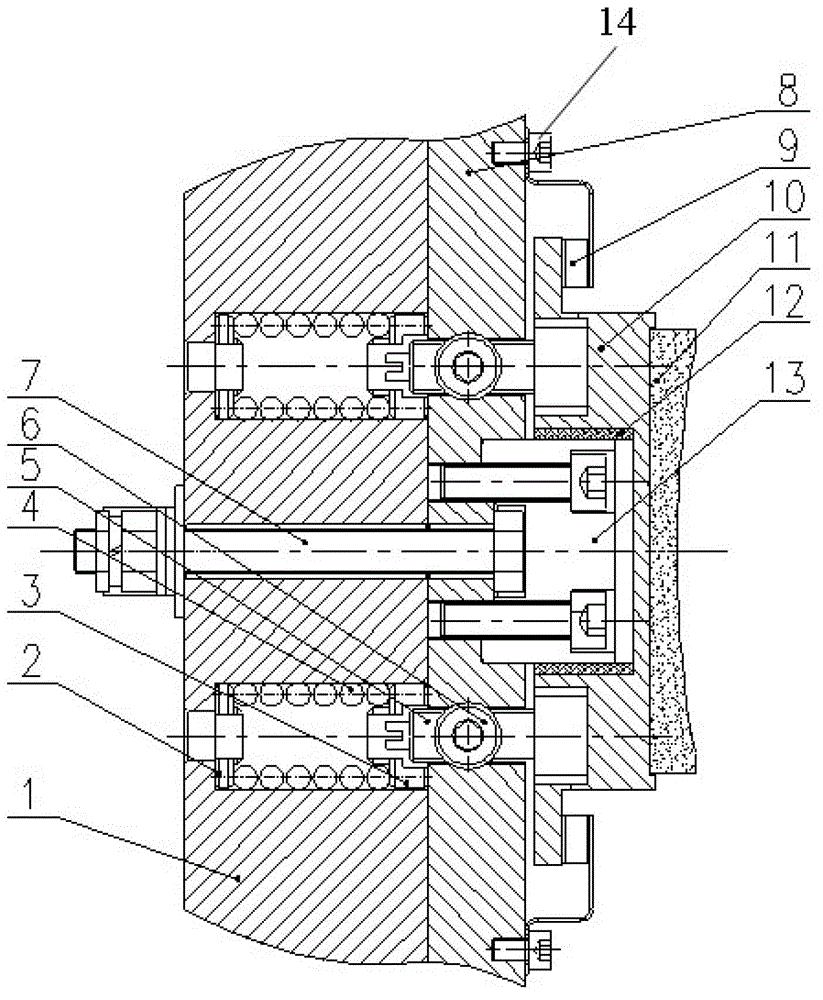
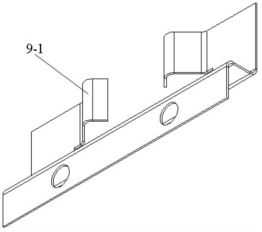
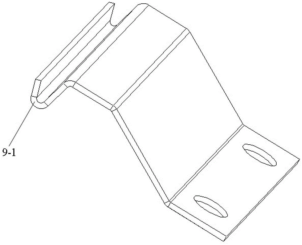
[0023] The accompanying drawings can represent the best embodiments of the present invention, and the detailed technical contents and embodiments of the present invention will be further described below in conjunction with the accompanying drawings. However, it should be noted that the symbols and embodiments shown in the drawings should not be regarded as limitations on the technology of the present invention, and any modification and addition on the basis of the present invention should be regarded as the scope of protection of the present invention.

[0024] see Figure 1-3 , The electromagnetic brake in this embodiment includes an electromagnet 1, an armature 8, a brake plate 10, and a brake pad 11. The brake electromagnet 1 and the armature 8 are connected by a central bolt 7, which is an outer hexagon half-threaded bolt. Under normal conditions, that is, when the brake is energized, the electromagnet 1 is attracted to the armature 8; when the brake is powered off and the...


PUM


Abstract

The invention discloses an electromagnetic brake which comprises an electromagnet (1), an armature (8), a brake plate (10) and a brake pad (11). The brake plate (10) is fixedly connected with the brake pad (11). The outer side of the brake pad (11) is of a recessed arc shape. The electromagnet (1) is connected with the armature (8) through a central bolt (7) and attached to a first side of the armature (8). The armature (8) is provided with an elastic recovery mechanism. The elastic recovery mechanism presses the brake plate (10) towards a second side of the armature (8). The armature (8) is fixedly connected with a guide shaft (13). The brake plate (10) is partially sleeved outside the guide shaft (13). The armature (8) is connected with an adjustable bolt (5) in a threaded manner. An end cap of the adjustable bolt (5) penetrates into an adjusting hole of the brake plate (10) and is in clearance fit with the same. The other end of the adjustable bolt (5) rightly faces and can penetrate into a through hole of the electromagnet (1). An elastic component (4) which generates outward acting force on the armature (8) is mounted in the through hole of the electromagnet (1). The brake pad component and the armature are separated and can rotate at a certain angle, and accordingly contact between a brake wheel and the brake pad can be adjusted automatically.

Description

technical field [0001] The invention belongs to the technical field of manufacturing electromagnetic brakes for elevator traction machines. It is used for direct braking of brake pads and brake wheels. The brake pads and armatures are designed separately and can be rotated at a certain angle for self-calibration of brake pad assemblies and brake wheels. At the same time, the brake pad assembly is restored through the elasticity of the compression spring. This design has not yet appeared in the existing electromagnetic brake industry. Background technique [0002] In view of the precise requirements of the elevator industry for the air gap of the brake, it takes too much energy to adjust the air gap between the brake electromagnet and the armature after the existing brake is installed. [0003] During the daily power-on and power-off operation of the brake, the accumulated errors in rotor runout, bearing precision, and manufacturing precision lead to eccentric wear of the bra...

Claims


Application Information

Patent Timeline
Patent Type & Authority Patents(China)
IPC IPC(8): B66D5/08B66D5/30
Inventor 徐璐杨银军游青平
Owner 浙江西子富沃德电机有限公司
Why Eureka
Try Eureka