

One-step spinning machine capable of conducting entwisting clockwise and one-step spinning method
A spinning machine and forward technology, which is applied in the field of forward multi-twist one-step spinning machine and one-step spinning, can solve the problems of high consumption, inability to achieve high-count, high-quality spinning, etc., and achieve reasonable structure and reduce spinning. The number of yarn processes and the effect of compact equipment
- Summary
- Abstract
- Description
- Claims
- Application Information
AI Technical Summary
Problems solved by technology
Method used
Image

Examples
Embodiment Construction
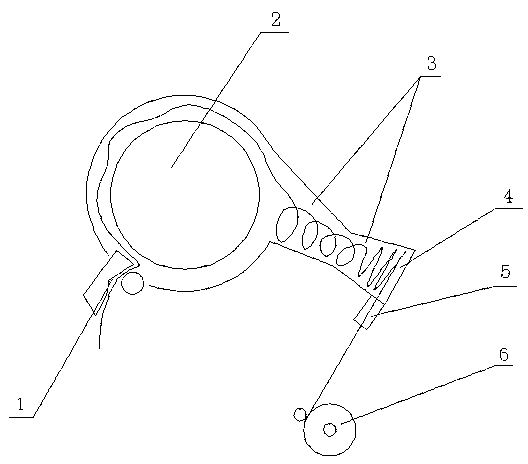
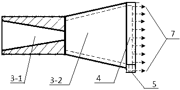
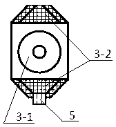
[0032] The present invention will be described in further detail below in conjunction with accompanying drawing and embodiment: See Figure 1-Figure 8 , an embodiment of a forward polytwisting one-step spinning machine of the present invention, comprising a frame, a carding roller 2, a carding roller cover, a fiber feeding mechanism 1, a forward cohesive twisting mechanism, and a yarn winding mechanism 6 And the air suction device, the opening roller 2 and the opening roller cover are arranged on the frame, the fiber feeding mechanism 1 is arranged on one side of the opening roller 2, and the other side of the opening roller 2 is provided under the other side which is connected with the opening roller cover. Shaped tube 3. The fiber feeding mechanism 1 is a cotton feeding roller and a cotton feeding board or a pair of wool feeding rollers. The special-shaped pipe 3 is formed by butt jointing of a tapered pipe 3-1 and a trapezoidal pipe 3-2, the large-diameter end of the taper...
PUM
| Property | Measurement | Unit |
|---|---|---|
| Outlet diameter | aaaaa | aaaaa |
Abstract
Description
Claims
Application Information