Counter pull type impact piling machine

A pile sinker and back-pull technology, which is applied to sheet pile walls, buildings, and foundation structure engineering, can solve the problems of easy cracking of pile tops, small impact energy of pile sinkers, and high pile frames, making it difficult to crack and break , reduce the height of the pile frame, the effect of compact structure

Inactive Publication Date: 2013-04-24
HUNAN UNIV OF SCI & TECH
View PDF4 Cites 2 Cited by
  • Summary
  • Abstract
  • Description
  • Claims
  • Application Information

AI Technical Summary

Problems solved by technology

[0003] Aiming at the above-mentioned defects existing in the existing impact pile driving machine, in order to solve the technical problems that the impact energy of the pile driving machine is small, the pile frame is too high, and the pile top is easy to crack, the present invention provides a reverse pull type impact pile driving machine

Method used


Image

  • Counter pull type impact piling machine
  • Counter pull type impact piling machine
  • Counter pull type impact piling machine

Examples


Embodiment Construction

[0023] The specific implementation manners of the present invention will be further described in detail below in conjunction with the accompanying drawings.

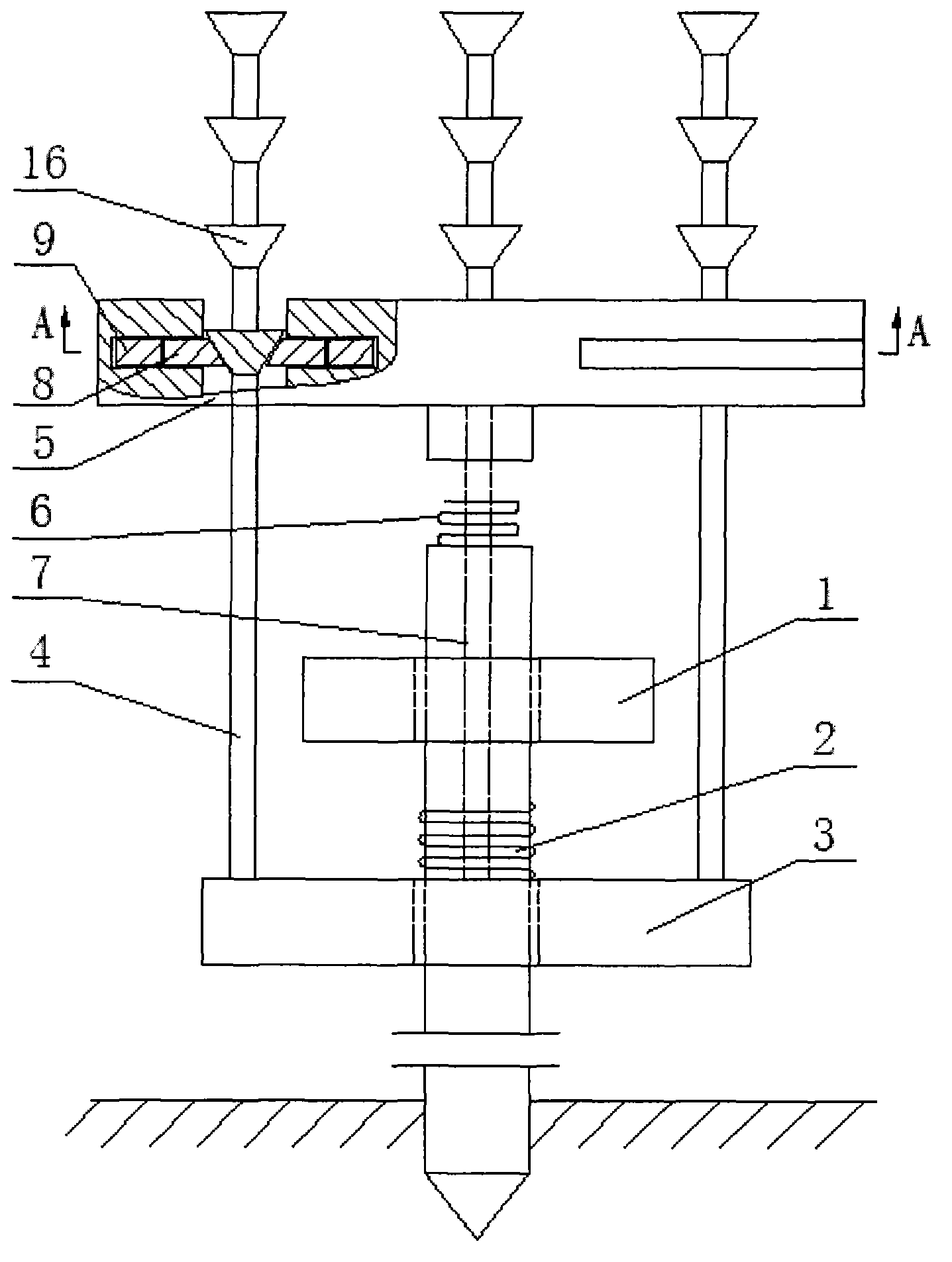
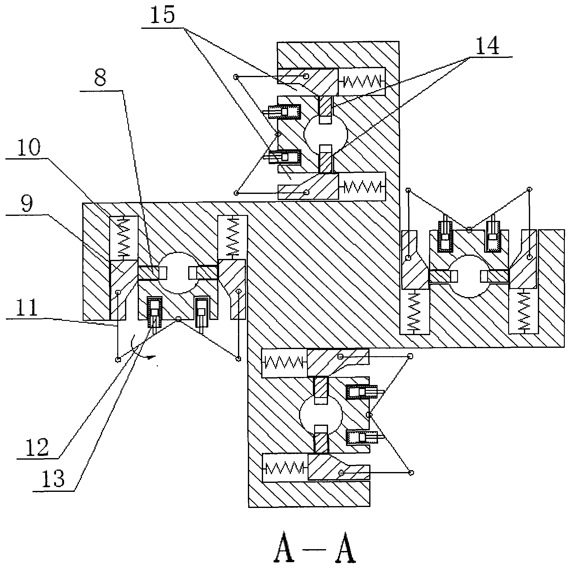
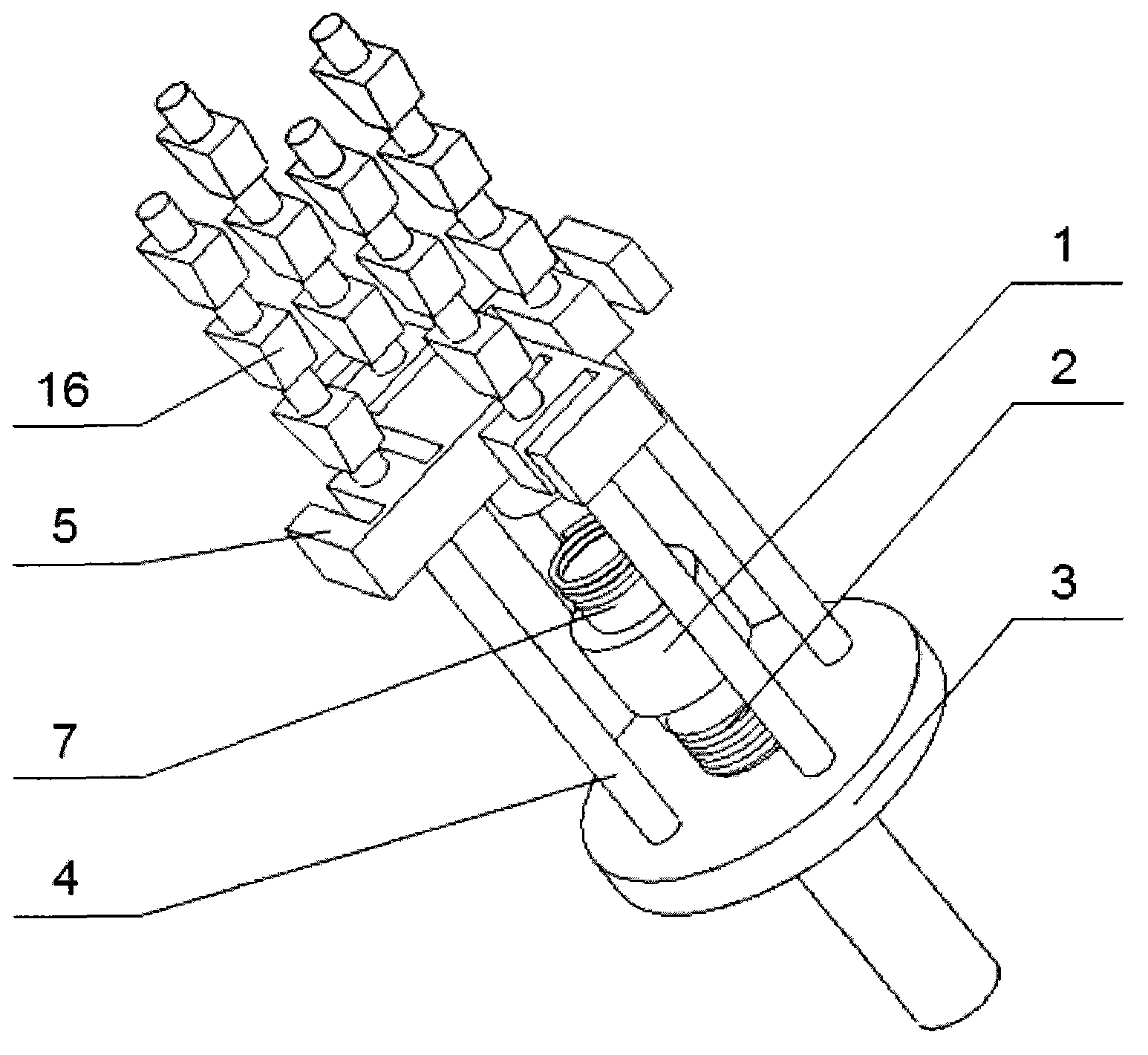
[0024] Such as figure 1 and image 3 As shown, the anti-pull impact pile driver of the present invention includes an impact hammer 1, a tension and pressure box 3, four pull rods 4, a pile cap 5, four sets of pull rod clamping mechanisms and a set of external power source (not shown) out). Among them, the impact hammer 1 is located above the tension and compression box 3, and both the impact hammer 1 and the tension and compression box 3 are provided with a coaxial central hole for the prefabricated pile 7 to freely pass through, and the external power source is connected with the impact hammer 1 to drive the impact. The hammer performs the impact. The pile cap 5 is located above the impact hammer 1, and four sets of pull rod clamping mechanisms are evenly distributed inside the pile cap 5, and each set of pull rod cl...


PUM


Abstract

The invention discloses a counter pull type impact piling machine. The counter pull type impact piling machine comprises an impact hammer (1), a tension and compression box (3) and an external motive power source, the external motive power source is connected with the impact hammer, coaxial center holes for enabling a preformed pile (7) to freely pass through are mounted on the impact hammer and the tension and compression box, the counter pull type impact piling machine further comprises a pile cap (5), at least two pull rods (4) and at least two sets of double inclined wedge surface pull rod clamping mechanisms, the pile cap is provided with at least two symmetrical branches, the double inclined wedge surface pull rod clamping mechanisms are in a one-to-one correspondence with the pull rods, and one set of pull rod clamping mechanism is disposed in each branch of the pile cap. Lower ends of the pull rods are fixedly connected with the tension and compression box, and upper ends of the pull rods penetrate through the pile cap and are adjustably connected with the pile cap through corresponding pull rod clamping mechanisms. A plurality of cone frustums (16) are disposed on the pull rods, a cushion pad (2) is sleeved on the tension and compression box, and a pile cushion (6) is arranged at a pile top. Each pull rod clamping mechanism comprises a V-shaped pin (9), an inclined wedge block (8), a connecting rod crank mechanism and an oil cylinder. Guide grooves for installing V-shaped pins and grooves for installing inclined wedge blocks are arranged in the pile cap, and reset springs are disposed at tail ends of the V-shaped pins. The counter pull type impact piling machine has the advantages of being capable of improving impact energy, reducing pile frame height and protecting the pile top of the preformed pile, compact in structure and widely applicable to various pile driving occasions.

Description

technical field [0001] The invention relates to an impact pile driving machine, in particular to a reverse pull type impact pile driving machine. Background technique [0002] The impact pile driver can generate a huge force pulse by using the impact, and it is more compact than the static pile driver, so it is widely used. Most of the current impact pile driving machines adopt the top hammering structure, that is, the use of hydraulic, steam, diesel and other energy sources to drive the piston and impact hammer, so that it can obtain a certain speed and hit the pile top of the prefabricated pile. Since these energy sources must be in a closed structure to generate driving force, the volume and quality of the impact hammer are limited, thereby restricting the improvement of the total impact energy. In addition, the impact velocity is obtained by using the free fall of the impact hammer. Although the impact hammer is not limited, the height of the pile frame of the pile driv...

Claims


Application Information

Patent Timeline
IPC IPC(8): E02D7/26
Inventor 杨书仪欧阳斌孙要兵刘德顺
Owner HUNAN UNIV OF SCI & TECH
Why Eureka
Try Eureka