Reversing device and reversing system for waste water heat exchange

A reversing device and non-clean water technology, applied in the energy field, can solve problems such as poor reliability, difficult processing, and unreachable applications, and achieve the effects of solving blockage and entanglement, stable and reliable operation, and safe operation

Active Publication Date: 2014-12-17
西安水务集团新能源有限公司
View PDF7 Cites 0 Cited by
  • Summary
  • Abstract
  • Description
  • Claims
  • Application Information

AI Technical Summary

Problems solved by technology

[0011] The purpose of the present invention is to provide a reversing device and system for non-clean water heat exchange, to solve the problem of dirt growth and blockage in the heat exchange equipment during heat exchange of non-clean water, and the existing technology is difficult to process, High precision requirements, poor reliability and problems such as failure to achieve the purpose of application when the valve body is large

Method used


Image

  • Reversing device and reversing system for waste water heat exchange
  • Reversing device and reversing system for waste water heat exchange
  • Reversing device and reversing system for waste water heat exchange

Examples


specific Embodiment approach 1

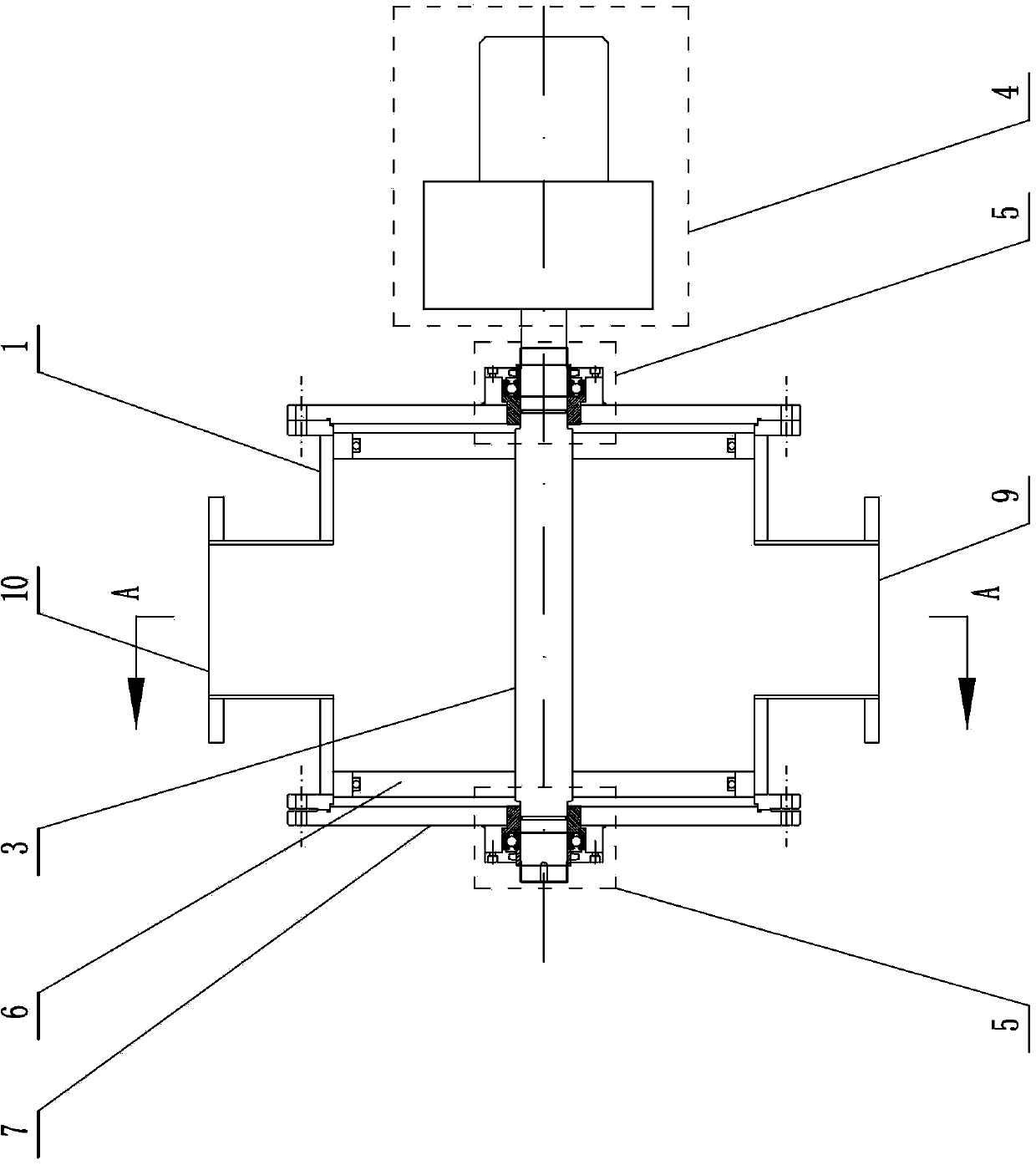
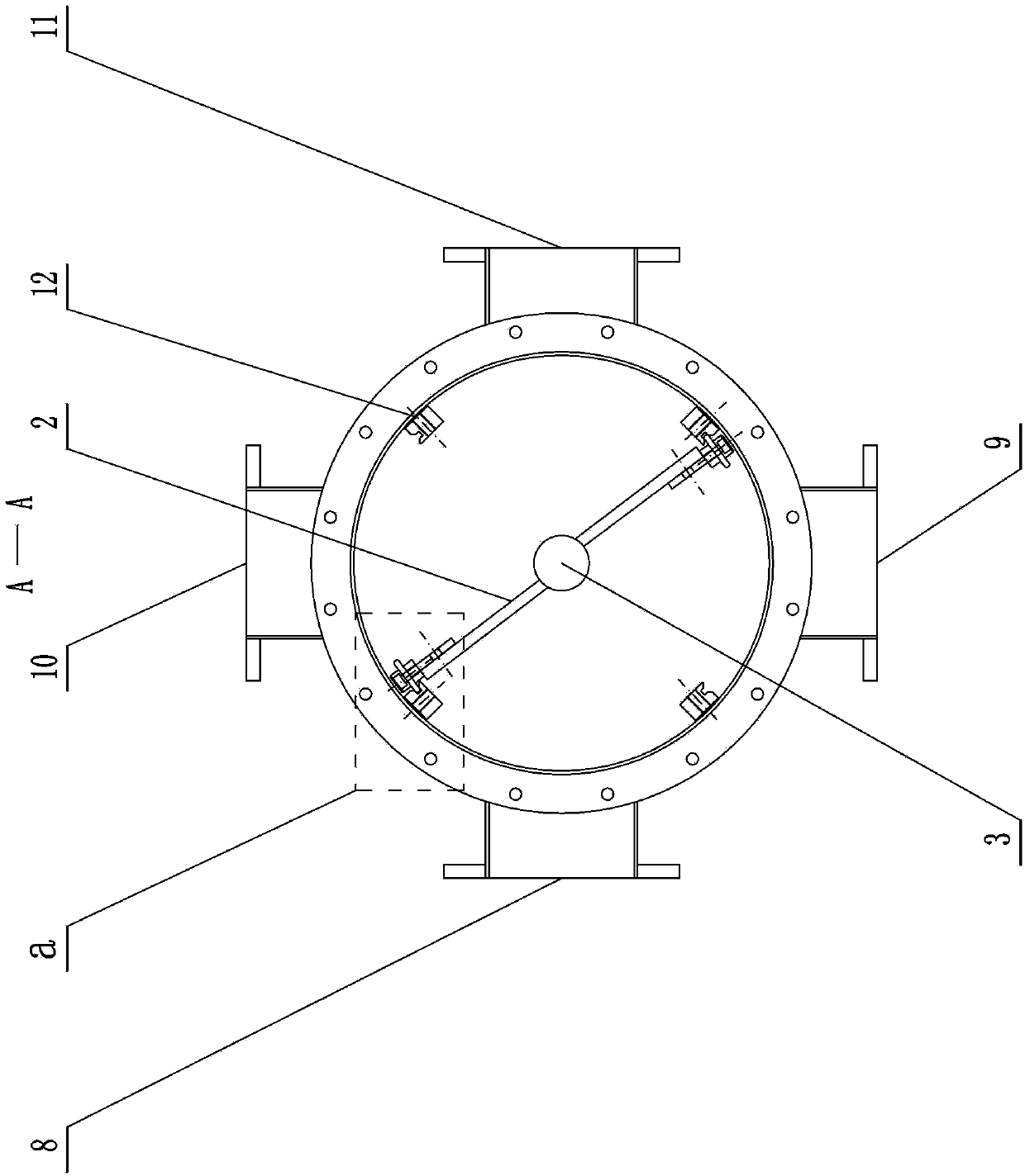
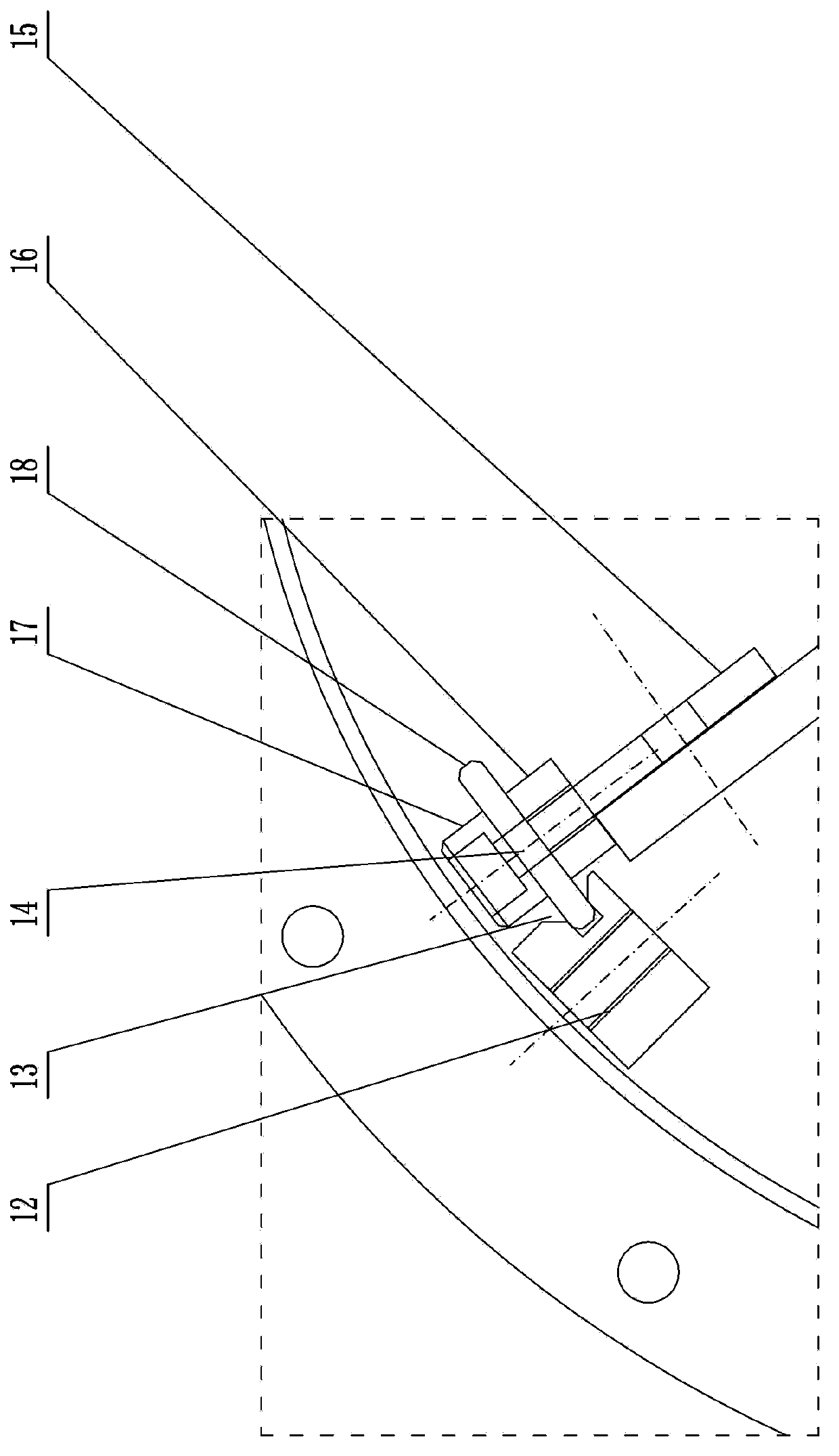
[0031] Specific implementation mode one: as Figure 1 ~ Figure 3 As shown, a reversing device for non-clean water heat exchange in this embodiment, the reversing device includes a housing 1, a valve plate 2, a rotating shaft 3, a decelerating drive mechanism 4, and two bearing seats 5 , two turntables 6, two flanges 7, water inlet 8, water outlet one 9, water outlet two 10, water outlet 11, four limit grooves 12, notch 13, rubber head 14, all The rubber head 14 includes a connecting plate 15, a terminal plate 16, a pressing plate 17 and a rubber strip 18, and the housing 1 is divided into four parts along the circumferential direction, and each part is connected with the water inlet 8, the water outlet and the return port 9 respectively. , the water outlet two 10 and the water outlet 11 are connected, and the water outlet one 9 and the water outlet two 10 are on both sides of the water inlet 8 and the water outlet 11 in the circumferential direction of the housing 1; the two s...

specific Embodiment approach 2

[0032] Specific implementation mode two: as Figure 4 As shown, a reversing device for non-clean water heat exchange in this embodiment, the water inlet 8 of the reversing device, the first water outlet and return port 9, the second water outlet and return port 10, and the drain port 11 are located in the housing 1 The top is at the same or different positions along the axial direction of the rotating shaft 3, and the others are the same as in the first embodiment. The pipe diameter of the drain port 11 is relatively large, and the size of the above-mentioned four ports in the circumferential direction of the housing 1 is limited. By arranging the four ports at different positions along the axial direction of the rotating shaft 3, the requirements of the housing 1 can be reduced. In addition, by arranging the four ports at different positions along the axial direction of the rotating shaft 3, the space required for connecting the four ports with the pipeline can be reduced.

specific Embodiment approach 3

[0033] Specific implementation mode three: as Figure 1 ~ Figure 4 As shown, a reversing device for non-clean water heat exchange according to this embodiment, the diameters of the water inlet 8, the water outlet one 9, the water outlet two 10 and the water outlet 11 of the reversing device are 100mm ~ 600mm.


PUM


Abstract

The invention relates to a reversing device and a reversing system for waste water heat exchange, belongs to the technical field of energy resource and solves the problem about fouling generation in heat exchange equipment and blockage and twisting of suspended matters during heat exchange of waste water and the problems that a reversing device and a reversing system of the prior art are high in processing difficulty, high in accuracy requirements and poor in reliability, and a big valve cannot achieve the application purpose and the like. The reversing device comprises a casing, a valve plate, four limit slots, notches and a rubber head. Soft sealing is realized by the aid of the limit slots and the rubber head. The reversing system comprises the reversing device, heat exchange equipment, a first water return pipe and a second water return pipe. A speed reduction driving mechanism acts to drive a valve plate to act so as to change water flow direction in the heat exchange equipment for reverse flushing. The reversing device and the reversing system are used for water flow direction changing in waste water heat exchange and reverse flushing of the heat exchange equipment and have the advantages of simple structure and reliability.

Description

technical field [0001] The invention relates to a heat exchange device and system for heat exchange of non-clean water (sewage, rivers and lakes, seawater, industrial waste water, industrial circulating cooling water, etc.), belonging to the field of energy technology. Background technique [0002] Using heat pump technology to extract cold heat from low-grade, renewable clean energy for heating and air conditioning of buildings is one of the effective ways to save energy and reduce emissions in buildings. These low-level renewable clean cold and heat sources include: groundwater, rivers and lakes, seawater, industrial wastewater, urban sewage, etc. Their temperature is between 0 and 30°C in winter. When they are used as cold and heat sources for heat pumps, the heat pump system The utilization efficiency of primary energy (coal, oil, natural gas) can reach 133% or higher, and the energy saving rate can be more than 45%. But when using these cold and hot energy sources, in ...

Claims


Application Information

Patent Timeline
Patent Type & Authority Patents(China)
IPC IPC(8): F16K27/02F16K1/46F16K11/052F28F19/01
Inventor 吴荣华迟芳王刚迟焕文
Owner 西安水务集团新能源有限公司
Why Eureka
Try Eureka