
Display support

A technology for display brackets and displays, which is applied in the direction of machines/stands, supporting machines, mechanical equipment, etc., can solve the problems of increased resistance and inability to rotate, and achieve the effects of increased resistance, labor-saving angle adjustment, and convenient adjustment

Active Publication Date: 2013-04-24
LOCTEK ERGONOMIC TECH CORP
View PDF8 Cites 21 Cited by
  • Summary
  • Abstract
  • Description
  • Claims
  • Application Information

AI Technical Summary

Problems solved by technology

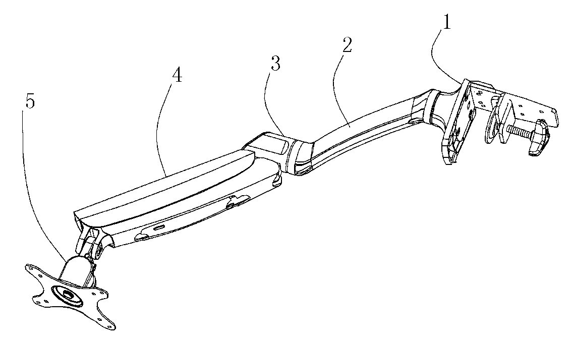
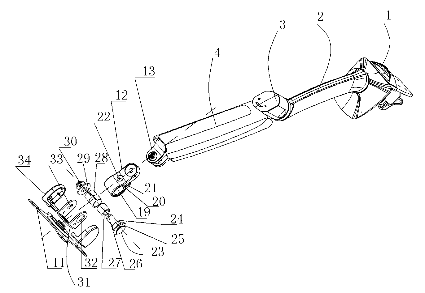
[0006] After adopting the above structure, compared with the prior art, the display stand of the present invention has the following advantages: the outer end of the connecting block of the display stand is provided with a shaft hole, and a rotating shaft is fitted in the gap of the shaft hole, and the rotating shaft A one-way bearing is connected to the top, and the outer circle of the one-way bearing is closely matched with the inner wall of the shaft hole. The one-way bearing is internally locked, so that the outer ring of the one-way bearing cannot rotate relative to the inner ring, and it rotates by overcoming the friction between the outer circle of the one-way bearing and the inner wall of the shaft hole, so the hanging plate and connection are added. The resistance to the downward rotation of the parts, so as to prevent the display from tilting downward due to its own weight; and when the display rotates downward with the hanging board and the connecting parts, the frictional resistance is stable, the adjustment is labor-saving and convenient, and there will be no need for further downward rotation. The greater the force, the more inconvenient the adjustment; when turning upward to adjust the angle of the display, the outer ring of the one-way bearing on the rotating shaft rotates relative to the inner ring, so that the upward rotation resistance of the hanging plate and the connecting piece is small, and the angle adjustment is labor-saving and convenient.

Method used


Image

  • Display support
  • Display support
  • Display support

Examples


Embodiment 1

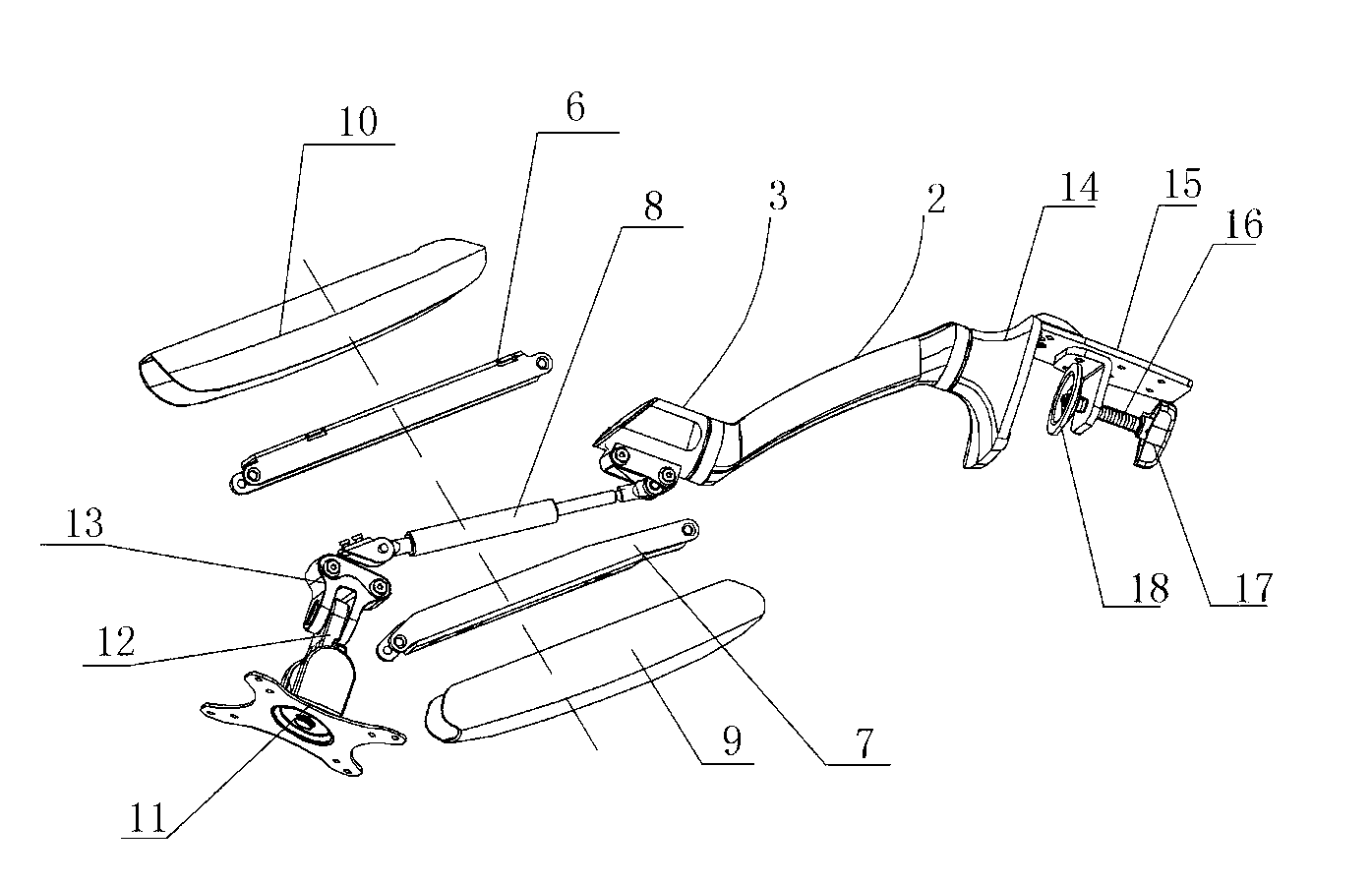
[0027] The display bracket of the present invention includes a bracket body with an adjustable angle and a display hanging board assembly 5, a connector 13 is connected to the bracket body, and the display hanging board assembly 5 includes a hanging board 11, a connecting piece 31 and a connecting block 12. The hanging plate 11 is rotatably connected to the connector 31, one end of the connecting block 12 is rotatably connected to the connecting head 13, and the other end of the connecting block 12 is provided with a shaft hole 19, and the shaft A rotating shaft 23 is fitted with clearance in the hole 19, and a one-way bearing 27 is connected to the rotating shaft 23. The outer circle of the one-way bearing 27 is closely matched with the inner wall of the shaft hole 19, and the two ends of the rotating shaft 23 are connected to the connector 31 fixed connections.

[0028] The side wall of the shaft hole 19 is provided with a longitudinal opening 20 passing through both ends, a...

Embodiment 2

[0037] Such as Image 6 Shown:

[0038] The fixing device 1 includes a base 14, and the base 14 is provided with screw holes fixedly connected with the installation surface by screws. The fixing device can be used by fixedly connecting the bracket body on an installation surface, such as on a wall.


PUM


Abstract

The invention discloses a display support. The display support comprises an angle-adjustable support body and a display hanging plate component (5). A joint (13) is connected on the support body. The display hanging plate component (5) comprises a hanging plate (11), a connector (31) and a connecting block (12), the hanging plate (11) is rotationally connected with the connector (31), one end of the connecting block (12) is rotationally connected with the joint (13), the other end of the connecting block (12) is provided with a shaft hole (19), a rotary shaft (23) is in close fit in the shaft hole (19), a one-way bearing (27) is connected on the rotary shaft (23), an outer circle of the one-way bearing (27) is in close fit with the inner wall of the shaft hole (19), and two ends of the rotary shaft (23) are fixedly connected with the connector (31). The display support is capable of protecting the hanging plate from downward inclining due to dead weight of a display and the angle of the hanging plate is laborsaving and convenient to adjust.

Description

technical field [0001] The invention relates to a monitor bracket. Background technique [0002] With the continuous development of society, monitors, tablet computers, etc. are becoming more and more popular in ordinary families. In order to save desktop or indoor space, matching brackets have emerged as the times require. For example, on the website of the State Intellectual Property Office, there is an invention patent named Omni-directional Free Arm Monitor Bracket. The disclosed technical solution includes: base, display hanging plate assembly, butterfly screw, first rocker arm and second rocker arm, The butterfly screw is connected to the base and is used to install the bracket on the desktop, one end of the first rocker arm is rotatably connected to the rotating shaft on the base, and the other end of the first rocker arm is rotatably connected to a connecting arm , one end of the second rocker arm is hinged to the connecting arm, the other end of the second rocker a...

Claims


Application Information

Patent Timeline
IPC IPC(8): F16M13/02F16M11/12
Inventor 项乐宏林涛蒋领辉
Owner LOCTEK ERGONOMIC TECH CORP
Learn More