
A sensing optical fiber ring and an all-fiber optic current transformer

A technology for sensing fiber optic rings and fiber optic rings, applied in polarized fibers, clad fibers, voltage/current isolation, etc., can solve the problems of affecting the measurement accuracy of current transformers, impracticality, and inability to distinguish output changes. The effect of optical path optical signal loss and optical polarization quality reduction, eliminating measurement errors, and improving the degree of integration

Active Publication Date: 2015-11-18
XI'AN INST OF OPTICS & FINE MECHANICS - CHINESE ACAD OF SCI
View PDF10 Cites 0 Cited by
  • Summary
  • Abstract
  • Description
  • Claims
  • Application Information

AI Technical Summary

Problems solved by technology

Because of this defect, the output change of the Sagnac sensor cannot be distinguished from the influence of the external environment or the change of the current itself in the high-voltage wire, which seriously affects the measurement accuracy of the current transformer and is not practical.

Method used


Image

  • A sensing optical fiber ring and an all-fiber optic current transformer
  • A sensing optical fiber ring and an all-fiber optic current transformer
  • A sensing optical fiber ring and an all-fiber optic current transformer

Examples


Embodiment Construction

[0028]The all-fiber current transformer uses the Faraday effect of the sensing fiber to achieve measurement, that is, the magnetic field around the measured current wire causes two beams of circularly polarized light with different rotation directions in the sensing fiber to transmit at different speeds to generate a phase difference. After measuring the interference The amplitude of the signal can indirectly measure the magnitude of the current in the wire. When two beams of circularly polarized light with opposite rotations pass through the magneto-optical fiber, due to the Faraday effect, the propagation speed of the two beams of circularly polarized light changes, causing the phase difference between the two beams to change. By measuring the change of the interference light intensity between two coherent beams of light, the magnitude of the wire current can be indirectly measured.

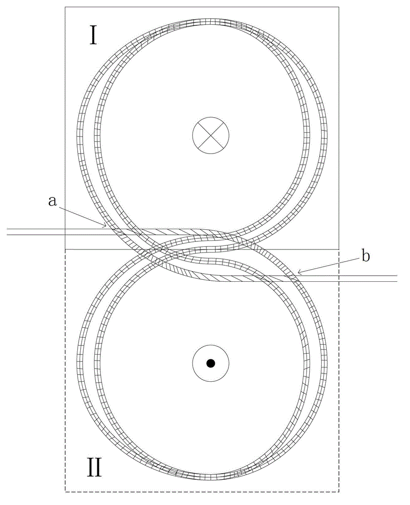
[0029] figure 1 It is a schematic diagram of the twisted optical fiber structure constitut...


PUM


Abstract

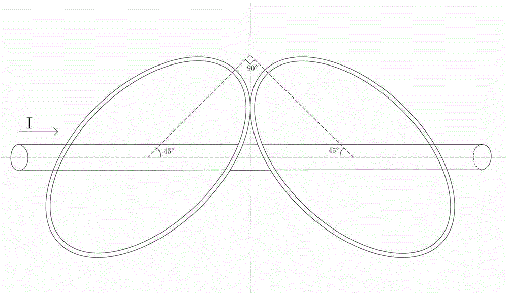
The invention provides a sensing optical fiber ring and an all-fiber current transformer. The sensing optical fiber ring comprises a twisted optical fiber, wherein the twisted optical fiber is wound on a coil skeleton in the shape of an '8' to form an optical fiber ring section I and an optical fiber ring section II which are opposite in winding direction, the axis of the optical fiber ring section I is perpendicular to the axis of the optical fiber ring section II, and an included angle between the axis of the optical fiber ring section I and a current wire and an included angle between the axis of the optical fiber ring section II and the current wire are both 45 degrees. The winding area of the optical fiber ring section I equals the winding area of the optical fiber ring section II, and the number of windings of the optical fiber ring section I equals the number of windings of the optical fiber ring section II. On the coil skeleton, the starting point of a starting rotation section and the starting point of a speed reducing rotation section of the twisted optical fiber are located at the same position, and the ending point of the starting rotation section and the ending point of the speed reducing rotation section of the twisted optical fiber are located at the same position. The symmetric center of the '8' is located at the central position of the sensing optical fiber ring. According to the sensing optical fiber ring and the all-optical fiber current transformer, the influence on the measurement of the all-optical fiber current transformer due to the performance of lambada / 4 wave plates is avoided, and meanwhile, measurement errors, caused by the Sagnac effect due to vibration, of the all-fiber current transformer are eliminated.

Description

technical field [0001] The invention relates to a sensing optical fiber structure and a manufacturing method thereof, and an all-fiber current transformer using the sensing optical fiber. Background technique [0002] With the continuous improvement of the voltage level and capacity of the power grid in the power system and the requirements of informatization, digitization, automation, and interaction of the smart grid, traditional current transformers have gradually exposed serious defects, and are increasingly unable to meet the requirements of power grids. The development requirements of the system, so the research of optical current transformer is imminent. A new type of all-fiber current transformer made of magneto-optical glass fiber made of magneto-optical glass is based on the Faraday effect, which can overcome the shortcomings of traditional current transformers to a certain extent and will gradually replace traditional ones. Current transformers have become one of...

Claims


Application Information

Patent Timeline
Patent Type & Authority Patents(China)
IPC IPC(8): G01R15/24G02B6/024
Inventor 王英利徐金涛刘尚波石念宝王嘉
Owner XI'AN INST OF OPTICS & FINE MECHANICS - CHINESE ACAD OF SCI
Learn More