Sound source localization method of three-dimensional space

A sound source localization, three-dimensional space technology, applied in the direction of positioning, measuring devices, instruments, etc., can solve the problems of insecurity, low accuracy of measuring sound source target distance, and high distance cost

Active Publication Date: 2013-04-24
HEBEI UNIV OF TECH
View PDF5 Cites 60 Cited by
  • Summary
  • Abstract
  • Description
  • Claims
  • Application Information

AI Technical Summary

Problems solved by technology

The method for measuring the sound source target adopted by the method of the present invention is a passive method, and the small-sized microphone array is moved in the measurement process, which overcomes the low accuracy of measuring the sound source target distance in the prior art and adopts the active method to measure the cost of the sound source target distance High is not safe

Method used


Image

  • Sound source localization method of three-dimensional space
  • Sound source localization method of three-dimensional space
  • Sound source localization method of three-dimensional space

Examples


Embodiment 1

[0101] A. The device used in this example

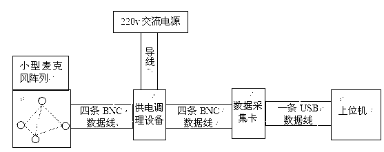
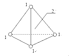
[0102] Including a small microphone array MPA201 microphone array, power supply conditioning equipment MC104, NI9215A data acquisition card and a PC with NIDAQ driver installed. The small microphone array is a regular tetrahedron with a radius of 10 cm circumscribed on the bottom surface. The microphone used is Beijing Renshengsheng The MPA201 microphone produced by Electric Technology Co., Ltd. uses the software matlab in the upper computer. The upper computer mainly includes the time delay calculation model, the azimuth angle calculation model, the elevation angle calculation model and the distance calculation model; each microphone and power supply conditioning equipment need a BNC connector The power supply conditioning equipment is connected to the entire microphone array through the 4 BNC connector data lines to power the latter. The power supply conditioning equipment is also connected to the data acquisition card through the 4 BN...

Embodiment 2

[0155] A. Equipment used in the method

[0156] The same as in Example 1.

[0157] B. In this implementation, the steps of using the above-mentioned device to locate a sound source in a three-dimensional space are:

[0158] Here the same as in Example 1.

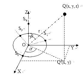
[0159] The first step is to determine the azimuth angle A of the sound source target before the small microphone array moves and the elevation angle E before the small microphone array moves

[0160] Here the same as in Example 1.

[0161] (1) Except that a small microphone array is used to collect the target sound signal for a period of 20ms, the others are the same as in Embodiment 1.

[0162] The result of the obtained relative delay estimation is: the time difference between microphone S2 and microphone S1 is 36, the time difference between microphone S3 and microphone S1 is 49, and the time difference between microphone S4 and microphone S1 is 28.

[0163] Since the acquisition card is 100k, the actual time represented by 36 here is...

Embodiment 3

[0193] B. In this implementation, the steps of using the above-mentioned device to locate a sound source in a three-dimensional space are:

[0194] Here the same as in Example 1.

[0195] The first step is to determine the azimuth angle A of the sound source target before the small microphone array moves and the elevation angle E before the small microphone array moves

[0196] Here the same as in Example 1.

[0197] (1) Except that the small microphone array is used to collect the target sound signal for a period of 30ms, the others are the same as in Embodiment 1.

[0198] The result of the obtained relative time delay estimation is that the time difference between microphone S2 and microphone S1 is 39, the time difference between microphone S3 and microphone S1 is 47, and the time difference between microphone S4 and microphone S1 is 28.

[0199] Since the acquisition card is 100k, the actual time represented by 39 here is 39 sampling periods, which is 39*10 -5 Seconds; 47 here repres...


PUM


Abstract

A sound source localization method of a three-dimensional space adopts a movable small microphone array and a sound source localization technology based on time delay estimation. The small microphone array is used for collecting a period of target sound source signals, a mutual correlation algorithm is used for calculating time differences between the microphones of the small microphone array, the time differences are substituted into computational formulas of azimuth and elevation to get the azimuth and the elevation of the target sound source, and then the small microphone array is moved for some distance along a certain azimuth, and the operations are repeated to get the azimuth and the elevation of the target sound source at the moment. Through measuring the azimuth and the elevation of the target sound source twice, the distance of the target sound source is calculated. The method of measuring target sound source is a passive method. The small microphone array is moved during the measuring process, and the defects that accuracy of the sound source target distance measuring of the prior art is low, and cost is high and safety is not ensured due to the fact that an active method is adopted to measure the sound source target distance are overcome.

Description

Technical field [0001] The technical solution of the present invention relates to a device that uses sound waves to determine the coordination of multiple directions, and specifically is a three-dimensional space sound source positioning method. Background technique [0002] Nowadays, with the continuous expansion of the application field of bionic technology, auditory perception technology based on microphone arrays has gradually become an important topic in many research fields such as mobile robot navigation, voice signal enhancement, and underwater target perception. It can be said that hearing is one of the important signs of a new generation of intelligent robots, and an important means to realize the "human-machine-environment" interaction. Because the sound has the characteristic of bypassing obstacles, in the multi-information collection system, hearing can be matched with vision, so as to compensate for the limited visual field of vision and the limitation of not passin...

Claims


Application Information

Patent Timeline
Patent Type & Authority Applications(China)
IPC IPC(8): G01S5/30
Inventor 杨鹏徐勤奇孙昊祖丽楠郑昀尹哲吴秀谦
Owner HEBEI UNIV OF TECH
Why Eureka
Try Eureka