Method for applying CAD (computer-aided design) drawing to precision finger-type milling cutter for involute gears

An application method, involute technology, applied in special data processing applications, instruments, electrical digital data processing, etc.

Inactive Publication Date: 2013-04-24
胡志祖
View PDF1 Cites 7 Cited by
  • Summary
  • Abstract
  • Description
  • Claims
  • Application Information

AI Technical Summary

Problems solved by technology

[0006] The purpose of the present invention is to provide a CAD drawing application method of involute gear precision finger milling cutter, which solves the complicated and easy calculation in the design process of precision finger milling cutter Error problems, to achieve the purpose of improving design accuracy, shortening product design cycle, reducing design cost, and avoiding design errors

Method used


Image

  • Method for applying CAD (computer-aided design) drawing to precision finger-type milling cutter for involute gears
  • Method for applying CAD (computer-aided design) drawing to precision finger-type milling cutter for involute gears
  • Method for applying CAD (computer-aided design) drawing to precision finger-type milling cutter for involute gears

Examples


Embodiment Construction

[0044] In conjunction with the accompanying drawings, the present invention is further described in detail through the embodiments.

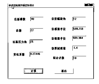
[0045] The CAD drawing application method of the involute gear fine finger milling cutter described in this embodiment is to construct a tool CAD system based on the UG platform for the actual production requirements of the involute gear fine finger milling cutter. By inputting the finger milling cutter Various 3D parameters of various 3D parameters are generated to generate 3D solid models. Through the analysis and summary of 3D parametric technology, the 3D model and 2D CAD graphics of involute gear fine finger milling cutter are realized by using parametric technology and UG secondary development technology. Automatic generation and automatic labeling of dimensions. The involute gear precision finger milling cutter includes straight teeth and helical teeth.

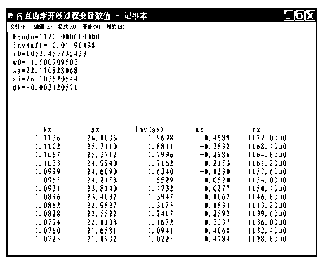
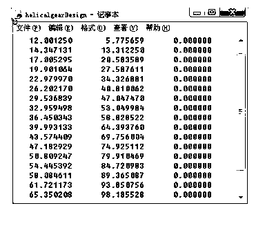
[0046] The process of generating the finger milling cutter is: input the parameters...


PUM


Abstract

The invention discloses a method for applying CAD (computer-aided design) drawing to a precision finger-type milling cutter for involute gears. The method is characterized in that a cutter CAD system is constructed on the basis of a UG (Unigraphics) platform, various three-dimensional parameters of the finger-type milling cutter are inputted to generate a three-dimensional entity model, a three-dimensional parameterization technology is analyzed and summarized, and purposes of automatically generating a three-dimensional model of the precision finger-type milling cutter for the involute gears and two-dimensional CAD graphs and automatically labeling dimensions are achieved by the aid of the parameterization technology and a UG secondary development technology. The method has the advantages that problems that computation is troublesome and errors are easy to make in a precision finger-type milling cutter designing procedure are solved, and purposes of improving the design precision, shortening a product design cycle, reducing the design cost and avoiding design errors are achieved. The method is widely applied to CAD parameterization design for finger-type milling cutters for machining gears according to a form copying principle and a non-instantaneous-pole envelope principle.

Description

technical field [0001] The invention belongs to the technical field of CAD parametric design of gear cutters, and mainly relates to an application method for CAD drawing of involute gear precision finger milling cutters. It is widely used in the CAD parametric design of finger milling cutters used for machining gears according to the principle of profiling method and the principle of non-instant center enveloping method. Background technique [0002] The traditional design of gear cutters requires a large amount of theoretical knowledge and a lot of related manuals to be consulted. The design process usually uses manual calculations, which are cumbersome, heavy workload and error-prone. [0003] At present, domestic gear cutting tools are mostly high-speed steel cutting tools, which are generally processed by ordinary machine tools, and there are many problems in processing efficiency and processing accuracy. The research and development trend of foreign gear cutting tools ...

Claims


Application Information

Patent Timeline
Patent Type & Authority Applications(China)
IPC IPC(8): G06F17/50
Inventor 胡志祖赵宗立张帮栋牛艳芳李玉辉
Owner 胡志祖
Why Eureka
Try Eureka