Photoelectricity composite cable with flexible metallic sheath

An optoelectronic integrated cable and metal sheath technology, applied in communication cables, cables, circuits, etc., can solve problems such as affecting the laying and use of integrated cables, affecting optical transmission performance, and poor flexibility, achieving low cost and product structure. Soft and good conductivity

Active Publication Date: 2013-04-24
JIANGSU ZHONGLI GRP CO LTD
View PDF12 Cites 27 Cited by
  • Summary
  • Abstract
  • Description
  • Claims
  • Application Information

AI Technical Summary

Problems solved by technology

Although the above-mentioned composite cables can achieve the purpose of transmitting electric energy and transmitting optical signals at the same time, their optical units are all formed by placing optical fibers in loose tubes. In order to protect the performance of optical fibers, they are usually placed in loose tubes. Filling in the water-blocking grease, the filling of the water-blocking grease affects the laying and use of...

Method used


Image

  • Photoelectricity composite cable with flexible metallic sheath
  • Photoelectricity composite cable with flexible metallic sheath
  • Photoelectricity composite cable with flexible metallic sheath

Examples


Embodiment 1

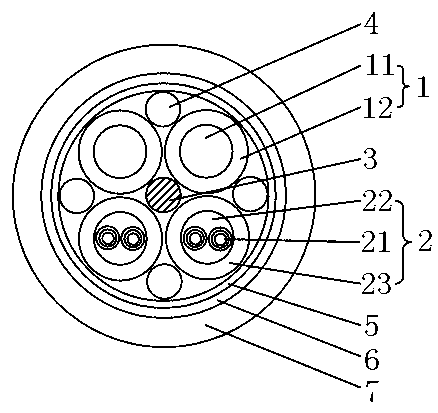
[0034] see figure 1 , an optoelectronic integrated cable with a soft metal sheath, which includes a central strengthening member 3, two feeders 1 distributed around the central strengthening member and two optical transmission units 2, and a cable covering the feeder and the optical transmission unit The cladding layer 5, the metal shielding armor layer 6 positioned outside the cladding layer, and the outer sheath 7 coated outside the metal shielding armor layer; the feeder 1 consists of a conductor layer 11 positioned inside and a The outer insulating layer 12 is formed; it is characterized in that the optical transmission unit 2 is composed of two tight-buffered optical fibers 21, a strengthening core 22 covering the tight-buffering optical fiber and a sheath layer 23 covering the strengthening core; the conductor The material of the layer is a soft conductor, and the material of the metal shielding armor layer is a corrugated aluminum tube; the soft conductor is a type 5...

Embodiment 2

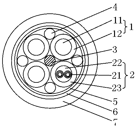
[0036] see figure 2 , an optoelectronic integrated cable with a soft metal sheath, basically the same as in Example 1, the difference is that there are three feeders, one optical transmission unit, and two tight-sleeved optical fibers in the optical transmission unit; The filling rope 4 is placed in the interval formed by the adjacent feeder, the optical transmission unit and the tape layer; the filling rope 4 is placed in the interval formed by the adjacent feeder and the tape layer.

Embodiment 3

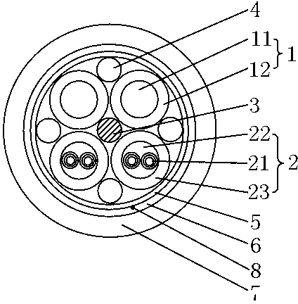
[0038] see image 3 , an optoelectronic integrated cable with a soft metal sheath, basically the same as in Example 1, except that there are two feeders, two optical transmission units, and two tight sleeves in each optical transmission unit Optical fiber; there is a tearing rope 8 between the cladding layer and the metal shielding armor layer that can tear the metal shielding armor layer and the outer sheath.


PUM

PropertyMeasurementUnit
Diameteraaaaaaaaaa

Abstract

The invention relates to the technical field of composition of optical cables and electric cables, in particular to a photoelectricity composite cable with a flexible metallic sheath. The photoelectricity composite cable with the flexible metallic sheath comprises a central strengthening piece, a plurality of feeder lines and a plurality of optical transmission units distributed around the central strengthening piece, a wrapping tape layer coated on the feeder lines and the optical transmission units, a metallic shield armor layer outside the wrapping tape layer, and an outer sheath coated outside the metallic shield armor layer, wherein each feeder lines is composed of an inner conductor layer and an outer insulation layer. The photoelectricity composite cable with the flexible metallic sheath is characterized in that the each optical transmission unit is composed of a plurality of tight-buffered optical fibers, a strengthening core coated outside the tight-buffered optical fibers, and a sheath layer coated outside the strengthening core. The conductor layers are made of flexible conductors. The metallic shield armor layer is made of a corrugation aluminum tube. The photoelectricity composite cable with the flexible metallic sheath has the advantages of being flexible in structure, easy to construct, and high in tensile strength.

Description

technical field [0001] The invention relates to the technical field of optical cable and cable compounding, in particular to a flexible photoelectric composite cable, which can not only transmit optical signals, but also realize power supply. Background technique [0002] In the prior art, there have been a lot of research and development on composite cables for transmitting electric energy and transmitting optical signals. For example, the name disclosed in CN201020622900.7 is a layer-twisted feeder cable, which includes a central strengthening member located in the center, and a central strengthening member surrounding the central strengthening member. The stranded body formed by twisting and the protective sheath wrapped outside the stranded body; the stranded body includes power lines and optical cables; the stranded body is stranded in an SZ manner around the central strength member; the power line is located in the central strength member outside, and tangent between t...

Claims


Application Information

Patent Timeline
IPC IPC(8): H01B11/22
Inventor 张喜生刘秋生王念立孙建宇刘焱鑫朱惠谢芳
Owner JIANGSU ZHONGLI GRP CO LTD
Why Eureka
Try Eureka