
Shield wiring base

A terminal block and terminal button technology, applied in the direction of connection, conductive connection, multi-core cable end components, etc., can solve the problem of not considering the influence of the frequency characteristics of the AC resistor of the terminal block, affecting the use power of the AC resistor and the accuracy of measurement It can achieve the effect of good economic value and environmental protection value, improved impact, and wide range of uses.

Inactive Publication Date: 2014-01-01
STATE GRID CORP OF CHINA +1
View PDF4 Cites 2 Cited by
  • Summary
  • Abstract
  • Description
  • Claims
  • Application Information

AI Technical Summary

Problems solved by technology

[0004] The key point affecting the frequency characteristics of the AC resistor is mainly the structure of the AC resistor, and the lead-out structure of the AC resistor is also one of the key points. At present, the design of the terminal block basically does not consider the inductance and capacitance introduced by the terminal block itself. The influence of frequency characteristics of AC resistors, especially the current bearing capacity and thermoelectric potential of materials are not considered when selecting materials, which affects the use power and measurement accuracy of AC resistors
For example, the Chinese patent application with the application number 201110142991.3 and the invention name "connector block" has proposed an improvement plan for anti-seismic measures, but it has not improved the influence of the inductance and capacitance introduced by the terminal block itself on the frequency characteristics of the AC resistor.

Method used


Image

  • Shield wiring base
  • Shield wiring base
  • Shield wiring base

Examples


Embodiment Construction

[0021] The invention will now be described in detail with reference to preferred embodiments of the invention as shown in the accompanying drawings. In the following description, several specific details are set forth in order to provide a thorough understanding of the present invention. It will be apparent, however, to one skilled in the art, that the present invention may be practiced without some or all of these specific details. In other instances, well known techniques have not been described in detail in order to avoid unnecessarily obscuring the present invention.

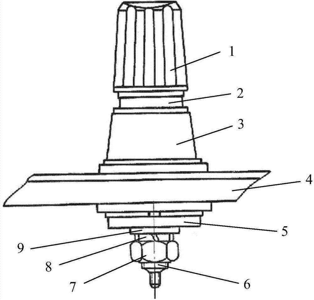
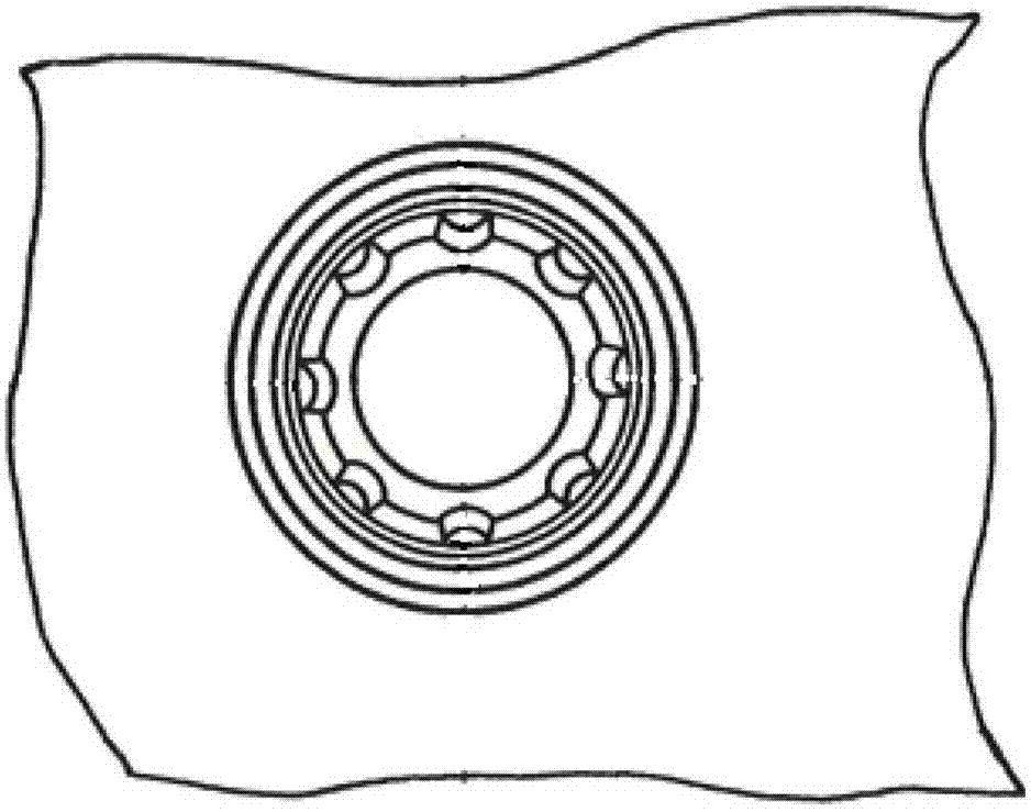
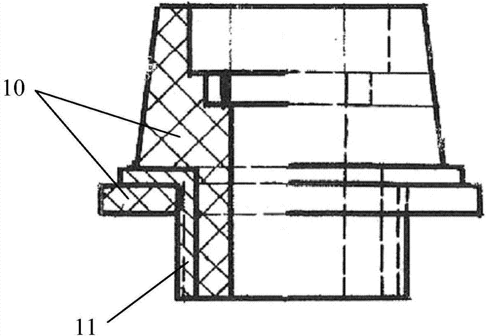
[0022] figure 1 A schematic side view of the shielded wire holder according to an embodiment of the present invention is shown. As can be seen from the figure, the shielded terminal block includes: terminal button 1, upper end gasket 2 of the shielded terminal base, upper end of the shielded terminal base 3, equipment panel 4, lower end of the shielded terminal base 5, conductive rod 6, hex nut 7, spring ...


PUM


Abstract

The invention relates to a circuit converting device, in particular to a shield wiring base. The shield wiring base aims to reduce or eliminate the adverse effect on the frequency characteristic of an alternating-current resistor from inductance and capacitance guided by the wiring base to the greatest extent, and improve use power of the alternating-current resistor. The shield wiring base mainly comprises the wiring base upper end, the wiring base lower end and a conducting rod, wherein the wiring base upper end is composed of an upper end metal ring and a polyoxymethylene material, the wiring base lower end is composed of a lower end metal ring and a polysulfone material, and the conducting rod penetrates through the wiring base upper end and the wiring base lower end, so that the upper portion of the conducting rod extends out of the wiring base upper end and the lower portion of the conducting rod extends out of the wiring base lower end. The shield wiring base is applied to alternating-current products, high-value direct-current resistance products and instruments with voltage less than 2kV, is wide in application range, improves the safety performance of electric appliances, and has good economic value and environmental protection value.

Description

technical field [0001] The invention relates to a circuit conversion device, in particular to a shielded terminal block. Background technique [0002] AC resistor products in electrical instruments and meters mainly include AC standard resistors, shunts, AC resistance boxes and impedance bridges for measurement. Since AC resistors are mostly used under AC conditions, they will be affected by factors such as distributed capacitance, distributed inductance, skin effect, and eddy current effect. In addition, the main technical feature of AC resistors is the addition of AC parameters to the technical specifications of DC resistors. Based on the above reasons, the accurate measurement of AC resistors has always been a difficult problem. At present, my country has not yet established a national standard for AC resistors. To ensure the accuracy and reliability of AC resistors during testing and use, it is necessary to improve the frequency characteristics of AC resistors and redu...

Claims


Application Information

Patent Timeline
IPC IPC(8): H01R9/00H01R11/11
Inventor 侯兴哲陈文礼王毅胡晓锐梁星孙恺霞
Owner STATE GRID CORP OF CHINA
Learn More