Scram button switch

A button and switch technology, applied in the direction of contact operating parts, etc., can solve the problems of complex structure and many accessories of emergency stop switch, and achieve the effect of simple structure and few accessories

Inactive Publication Date: 2013-04-24
YUEQING XINDALI IND CO LTD
View PDF6 Cites 8 Cited by
  • Summary
  • Abstract
  • Description
  • Claims
  • Application Information

AI Technical Summary

Problems solved by technology

[0005] For this reason, the technical problem to be solved by the present invention is that the existing emergency stop switch has a complex

Method used


Image

  • Scram button switch
  • Scram button switch
  • Scram button switch

Examples


Embodiment 1

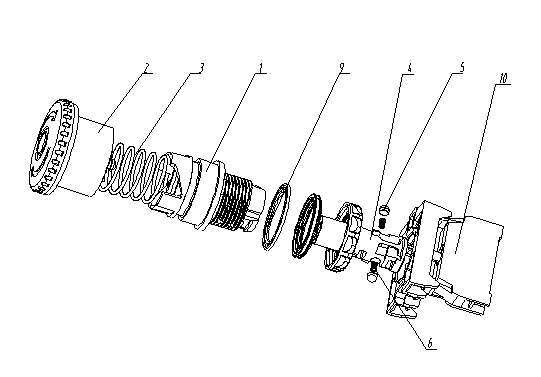
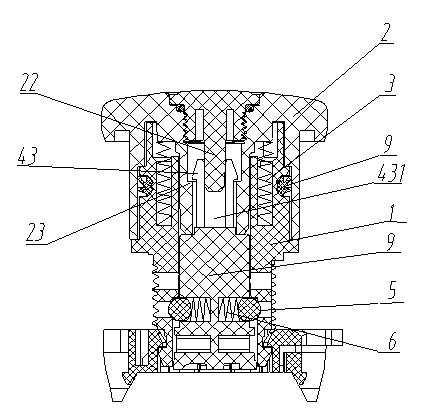
[0037] Such as figure 1 , figure 2 , image 3 , Figure 8 , Figure 9 Shown is the emergency stop button switch of the present invention, which includes a housing 1, a button 2, an operating member 4 and a locking device, wherein the operating member 4 is slidably arranged inside the housing 1, and the operating member One end of 4 is connected to the button 2, and a return spring 3 is arranged between the button 2 and the housing 1; the other end of the operating part 4 controls the contact or non-contact of the dynamic and static contacts in the base 10 to realize The circuit is switched on and off; the locking device is arranged between the operating member 4 and the housing 1, the locking device includes a slot 7 formed on the housing 1, and is arranged on the operating member 4 The locking piece 5 and the elastic piece 6 in the transverse groove 41; the locking piece 5 is a strip-shaped part, one end of which is a working end, and the working end is suitable for bein...

Embodiment 2

[0046] This embodiment is a preferred form of the above embodiment, the locking member 5 is a cylinder with both ends of an arc surface structure, one end surface is a hemispherical surface, and the other end surface is an arc surface with a radius of curvature greater than the radius of the hemispherical surface , when the hemispherical side is matched with the slot 7, the cylinder is in point contact with the edge of the slot 7, and when the arc side is matched with the slot 7, the cylinder and the slot The upper end surface of the card slot 7 is in contact.

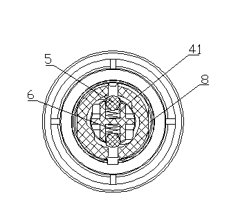
[0047] When the emergency stop button switch is set to pull type, as image 3 As shown, the arc surface end of the hemispherical surface of the locking member 5 is the working end, and the other end of the locking member 5 is connected to the elastic member 6. When locking, the hemispherical surface side cooperates with the card groove 7 , the cylinder is in point contact with the edge of the slot 7 .

[0048] When t...

Embodiment 3

[0050] This embodiment is the preferred mode of embodiment 1, such as Figure 5 and Figure 6 As shown, the locking member 5 is a circular frustum with both ends of the arc surface structure. In contact, when the arc surface on the side with a larger cross section fits with the locking groove 7 , the frustum of the cone contacts the upper end surface of the locking groove 7 . The radius of curvature of the arc surface on the side with the smaller cross section is smaller than the radius of curvature of the arc surface on the side with the larger cross section.

[0051] When the emergency stop button switch is set to pull type, as Figure 5 As shown, the arc surface end on the side with a small cross-sectional area of ​​the locking member 5 is the working end, and the arc surface on the side with a large cross-section of the locking member 5 is connected to the elastic member 6. When locking, the locking The arc surface end on one side with a small cross-sectional area of ​​...


PUM


Abstract

The invention discloses a scram button switch which comprises a shell body and a locking device, wherein an operating part is arranged inside the shell body. One end of the operating part is connected with a button, and a reset spring is arranged between the button and the shell body. The other end of the operating part controls contact or non-contact of a dynamic contact and a static contact in a base so as to achieve opening and closing of a circuit. The locking device is arranged between the operating part and the shell body. The locking device is composed of a clamping groove, a locking part and an elastic part, wherein the clamping groove is formed in the shell body, and the locking part and the elastic part are arranged in a horizontal groove of the operating part. The locking part is a long-strip-shaped part, one end of the locking part is a working end, and the working end is adapted to being clamped in the clamping groove under the function of the elastic part and locks the operating part. Under the function of traction/rotation of the button, the locking part quits from the clamping groove and unlocks the operating part. Both ends of the locking part are working ends and arc surfaces. When one end of the locking part is matched with the clamping groove, the one end is suitable for being contacted with the upper end face of the clamping groove. The other end of the locking part is suitable for being contacted with an edge point of the clamping groove. The scram button switch solves the technical problems of complex structure and multiple accessories.

Description

technical field [0001] The invention relates to an emergency stop switch, in particular to an emergency stop button switch. Background technique [0002] The emergency stop switch is a kind of master control electrical appliance. When the machine is in a dangerous state, the emergency stop switch is used to cut off the power supply and stop the operation of the equipment to protect the safety of people and equipment. The emergency stop switch is usually a manually controlled push switch, which is connected in series to the control circuit of the equipment. In an emergency, the power supply of the control circuit is directly disconnected to quickly stop the equipment to avoid abnormal operation. The emergency stop switch is generally divided into self-locking type and push-pull type. These two forms of emergency stop switches are locked by pressing the mushroom head button to its terminal position when locking; The self-locking emergency stop switch needs to rotate the mushr...

Claims


Application Information

Patent Timeline
IPC IPC(8): H01H3/02
Inventor 刘玉柱
Owner YUEQING XINDALI IND CO LTD
Why Eureka
Try Eureka