Pneumatic radial tire for automobiles

A radial tire, passenger car technology, applied in the reinforcement layer of pneumatic tires, special tires, tire parts, etc., can solve the problems of poor fuel consumption, sacrificing vehicle space, and deteriorating interior comfort, and achieve interior comfort. and the effect of excellent uneven wear resistance and low fuel consumption

Active Publication Date: 2013-04-24
BRIDGESTONE CORP
View PDF5 Cites 9 Cited by
  • Summary
  • Abstract
  • Description
  • Claims
  • Application Information

AI Technical Summary

Problems solved by technology

[0003] However, a larger tire width sacrifices vehicle space and therefore interior comfort will be degraded
In addition, there is a problem of poor fuel consumption due to increased air resistance

Method used


Image

  • Pneumatic radial tire for automobiles
  • Pneumatic radial tire for automobiles
  • Pneumatic radial tire for automobiles

Examples


Embodiment Construction

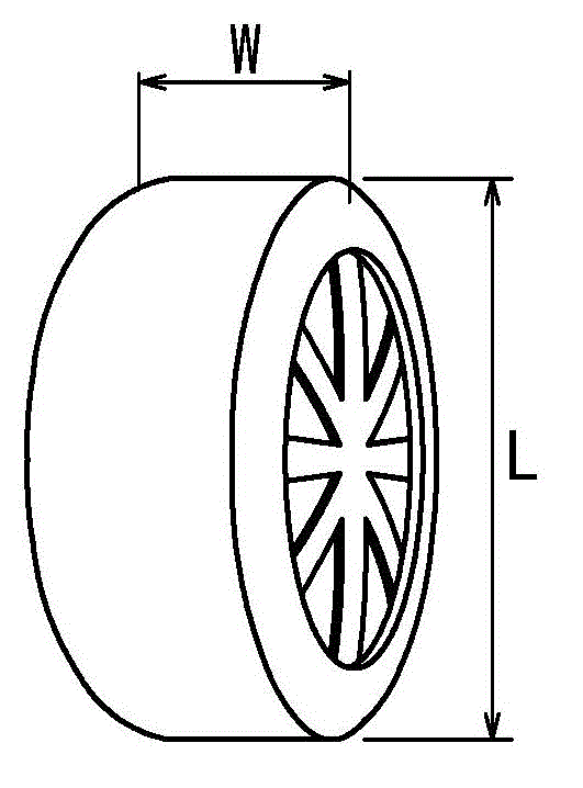
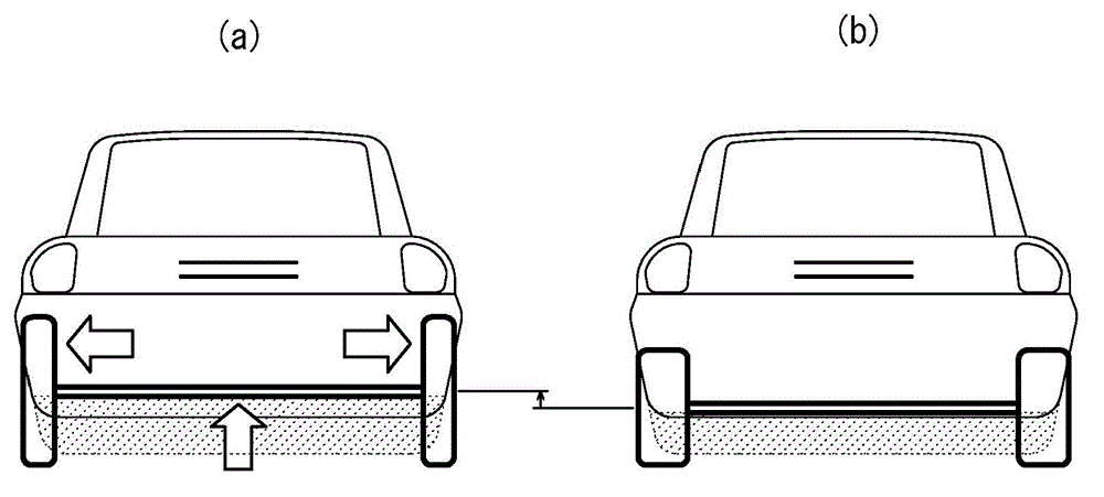
[0033] The process leading to the development of the pneumatic radial tire for passenger vehicles according to the present invention is described below. First, the inventors focused on how figure 1 The section width W of the radial tire is shown above, and it is found that by making the section width W as figure 2 As shown, the cross-sectional width of the tire is narrower than that of a conventional tire, and it is possible to ensure an internal space, especially a space for arranging drive components near the inner side of the tire mounted on a vehicle. In addition, a tire having a narrower section width W has a smaller area viewed from the front of the tire (hereinafter referred to as front projected area), which produces an effect of reducing air resistance of the vehicle. However, this involves a large deformation of the ground contact portion, causing the problem of a tire having a large rolling resistance at the same air pressure.

[0034] Furthermore, the inventors ...


PUM


Abstract

A pneumatic radial tire for a passenger vehicle has a ratio W / L where W is a cross-sectional width and L is an outer diameter. The tire also has a belt-reinforcing layer having a high rigidity and disposed between a belt and a tread.

Description

technical field [0001] The present invention relates to a pneumatic radial tire for passenger vehicles, and more particularly, to a tire for an electric vehicle capable of simultaneously improving low fuel consumption, interior comfort, and uneven wear resistance. Background technique [0002] Before the 1960s, vehicles were lighter and the required speeds of the vehicles were lower, so there was less load on the tires. Therefore, bias tires having a narrower section width have been used. Now, due to the heavier weight and higher speed of vehicles, tires having a radial structure and a larger width have been widely produced (see Patent Document 1). Compared with bias tires, tires applied with a radial carcass have excellent uneven wear resistance due to the higher rigidity of the crown portion of the tire. In addition, rolling resistance is reduced because the high rigidity of the crown portion suppresses transmission of motion of tire constituent members. For this reason...

Claims


Application Information

Patent Timeline
Patent Type & Authority Applications(China)
IPC IPC(8): B60C9/22B60C3/04B60C9/18B60C9/20
CPCB60C11/0332B60C3/04B60C9/2009B60C9/18B60C9/2204B60C2009/2266B60C9/22B60C9/20Y02T10/86
Inventor 桑山勲
Owner BRIDGESTONE CORP
Why Eureka
Try Eureka