Mop

A mop and roller technology, applied in the field of mops, can solve the problems of stains left on the surface, inability to reciprocate mopping, stains, etc., achieve good erasing, reduce the number of times to clean the mop, and increase friction

Active Publication Date: 2015-01-14
阳珉
View PDF8 Cites 0 Cited by
  • Summary
  • Abstract
  • Description
  • Claims
  • Application Information

AI Technical Summary

Problems solved by technology

The common disadvantage of the common mop in the market is that when using the mop to clean the surface to be cleaned, the mop itself will become dirty after cleaning a small area, and it is easy to leave stains on the cleaned surface
Especially when the ground is dirty and needs to be mopped back and forth, it is more likely to cause stains and dirt to spread around with the movement of the mop, and it needs to be mopped again, but at this time the sewage and dirt will be brought back, making the mopping more dirty phenomenon occurs, thus having to clean the mop several times during one use
[0003] In order to overcome the above-mentioned shortcomings, someone has designed a mop with a wiping roller. One of the solutions is that the mop moves in a single direction and the mop moves in a single direction, and stops when it moves in the other direction. The mop of this solution can only mop the floor in one direction and cannot be mopped back and forth. It is not easy to remove stubborn dirt on the ground, and after the mop’s wiping roller rolls to one side, the dirt will be left in place; another solution is to use manual control. The locking mechanism makes the wiping roller stop when mopping the floor, and only rotates when the water needs to be squeezed. When the surface of the wiping roller is dirty, the locking mechanism is operated again to make the uncontaminated surface of the wiping roller turn to the position in contact with the ground, such as Chinese patent 200710137592.1, although this kind of scheme can drag and wipe in two directions, but the structure is relatively complicated, and the operation is not very convenient
Although the above scheme can make full use of the surface of the wiping roller, due to the limited surface area of ​​the wiping roller, the wiping material on the surface of the wiping roller will still get dirty very quickly. The wiped ground is dirty and requires repeated mopping or frequent cleaning of the mop, which is time-consuming and laborious

Method used


Image

  • Mop
  • Mop
  • Mop

Examples


Embodiment 1

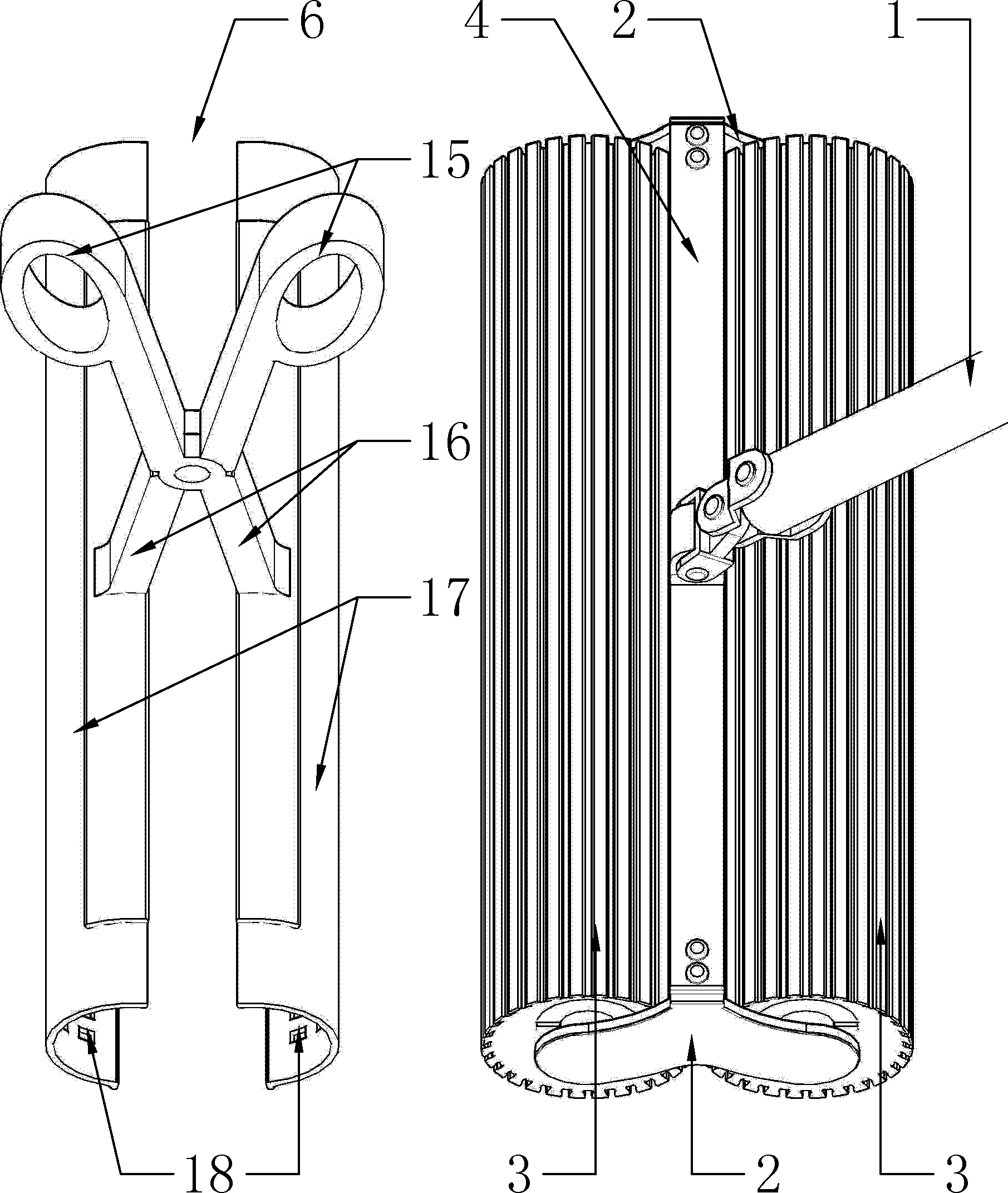
[0023] Embodiment 1: as figure 1 , figure 2 As shown: the lower end of the handle bar 1 is rotationally connected with the beam 4 on the bracket 2, the bracket is a two-piece flat plate structure reinforced by the beam, the beam and the bracket are detachably connected, preferably screwed, and the wiping roller 3 is divided into front and rear Two rows are arranged in parallel, each row has a wiping roller, and the two parallel structures of the bracket are located at the left and right ends of the two rows of wiping rollers.

[0024] The bracket is made of rigid material, and its material can be engineering plastics, metal, bamboo, wood, composite materials, etc., preferably engineering plastics in this embodiment, and a flexible protective cover can also be put on the rigid material, such as putting on A layer of soft glue to prevent scratches on furniture and corners.

[0025] The wiping roller comprises an inner layer support cylinder 9 and an outer layer wiping materia...

Embodiment 2

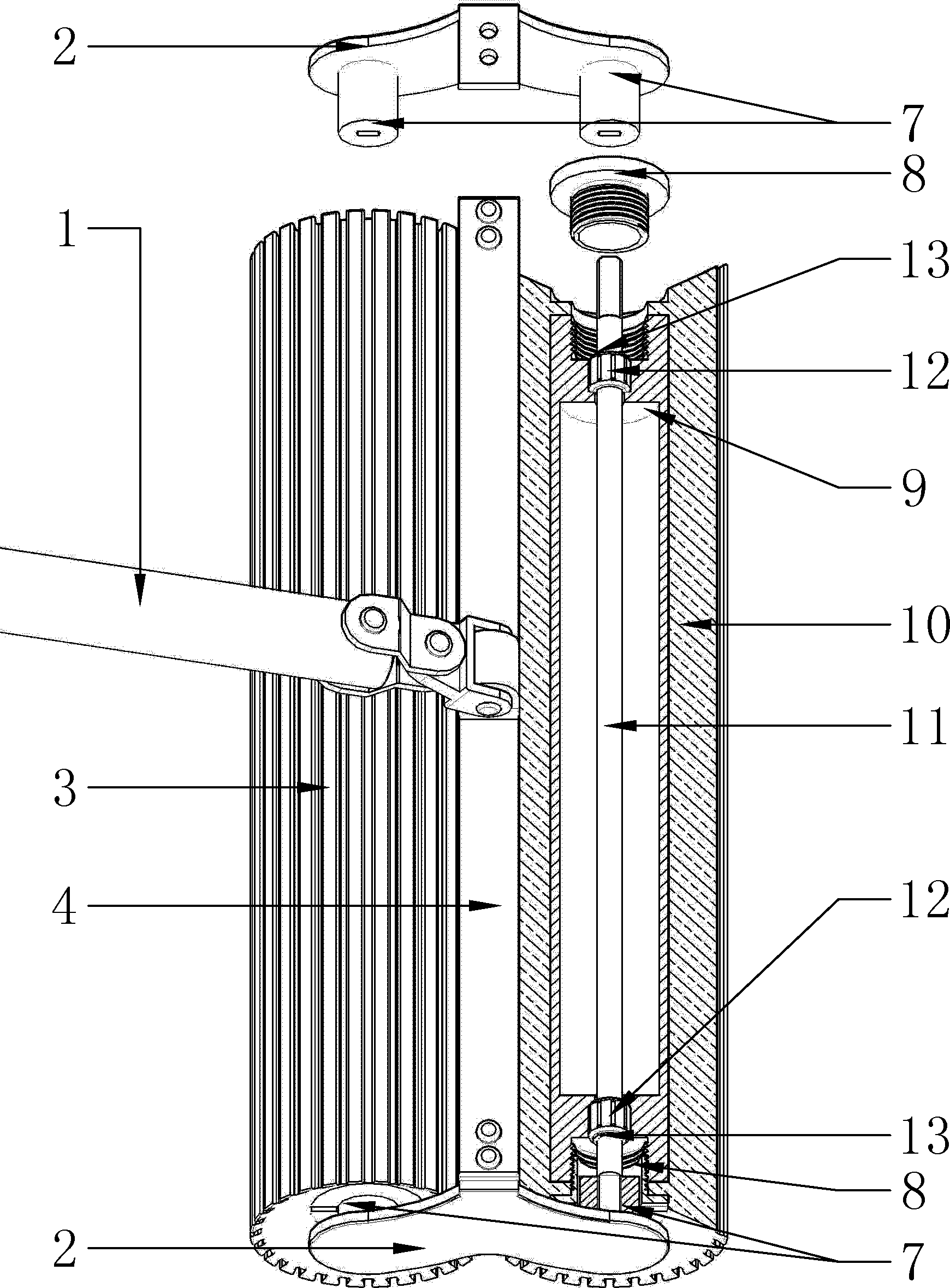
[0032] Embodiment 2: as image 3 , Figure 4 As shown, the handle bar 1 is rotationally connected with the bracket 2 through the L-shaped connecting arm 22 fixed thereon, and the wiping rollers 3 are arranged in parallel in front and rear rows, each row has a wiping roller, and the bracket is a flat plate structure located on the Wipe one end of the roller in two lines. This kind of connection method is adopted between the handle bar and the bracket, which can easily drag and wipe the corners and prevent damage to furniture and walls.

[0033] The wiping cylinder includes an inner support cylinder 9 and an outer layer of wiping material 10 coated on the surface of the inner support cylinder. The inner support cylinder is made of rigid material, preferably engineering plastics in this embodiment; the outer layer of wiping material can be made of flexible The water-absorbing material can also be made of flexible water-absorbing material and then covered with water-absorbing fa...

Embodiment 3

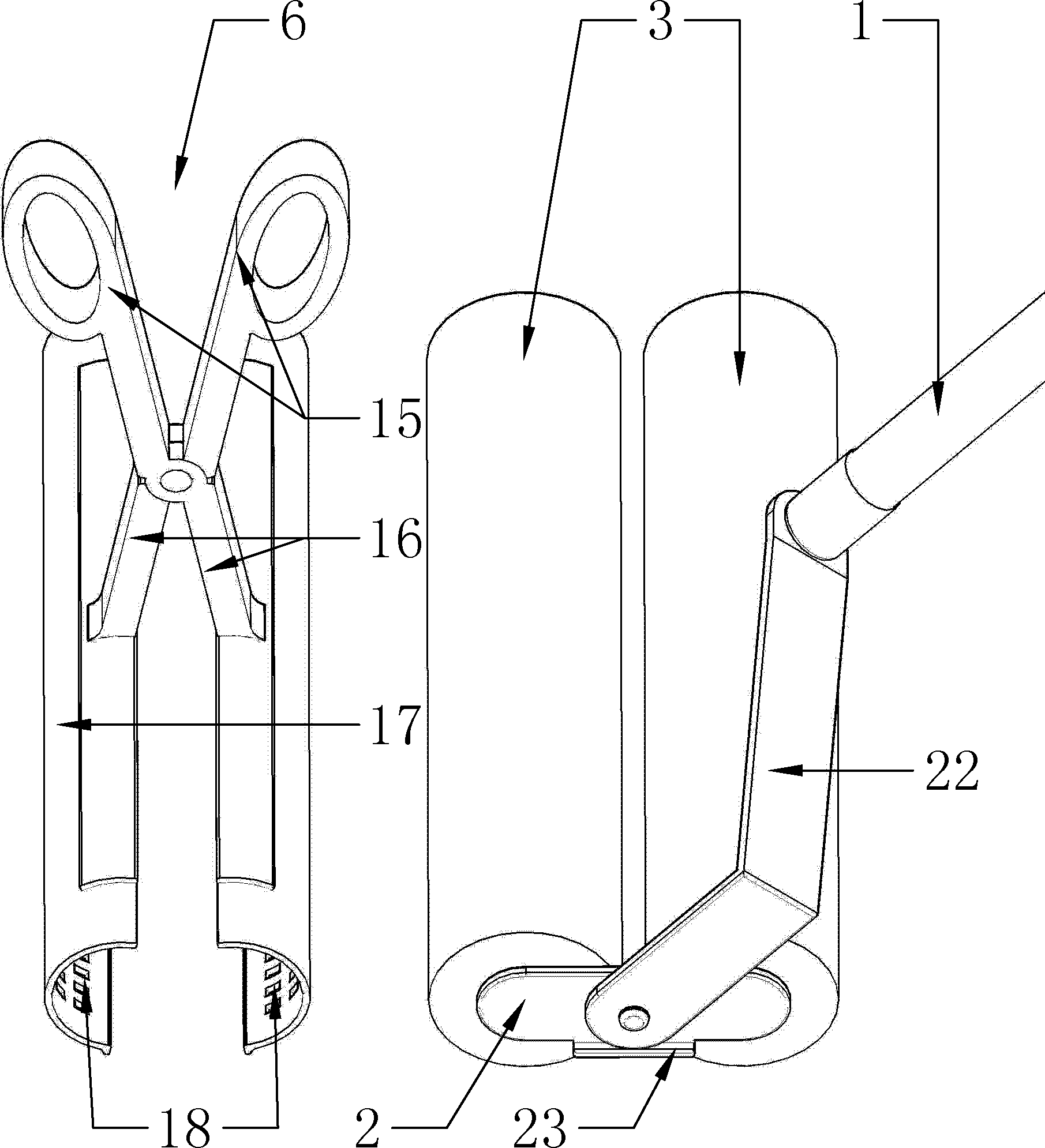
[0039] Embodiment 3: as Figure 5 , Figure 6 As shown, the lower end of the handle bar 1 is rotationally connected with the bracket 2, and the four wiping rollers 3 are arranged in parallel in front and rear rows, each row has two wiping rollers, the bracket 2 is a flat plate structure, and the two wiping rollers located in each row middle. This kind of connection method is adopted between the handle bar and the bracket, which can easily drag and wipe the corners and prevent damage to furniture and walls.

[0040] The wiping roller comprises an inner layer support cylinder 9 and an outer layer wiping material 10 coated on the surface of the inner layer support cylinder. The inner layer support cylinder is made of a rigid material, preferably engineering plastics in this embodiment; the outer layer wiping material is made of flexible water-absorbing The material composition can also be composed of flexible water-absorbing material and then covered with water-absorbing fabric...


PUM


Abstract

The invention discloses a mop which comprises a holding rod, a bracket connected to the lower end of the holding rod, and two rows of wiping rollers, wherein the two rows of wiping rollers are arranged on the bracket in parallel back and forth and can unidirectionally rotate; non-return directions of the wiping rollers in front and back rows are opposite; when the mop pushes forwards, the roller in the front row rolls forwards to wet the ground, and the roller in the back row stops for wiping the ground; and when the mop is pulled backwards, the roller in the back row backwards rolls to wet the ground, and the roller in the front row stops to wipe the ground. In the mopping process, the surfaces of the wiping rollers can be fully utilized; even if the rollers are dirt, falling dirt in the rolling process can be collected by the roller in a stopping state and is limited between two rows of rollers, so that the phenomena that the dirt and stain are distributed along the movement of the mop can be reduced or avoided, and the times of cleaning the mop in the mopping process can be reduced. The mop further comprises a wringer arranged in a separating manner. The wringer is of a tong-shaped structure with a simple structure; when the wringer is operated, the damage of the wringer to the rollers is little; when the wringer is damaged or lost, the wringer is only needed to be independently replaced; and the wringer can be also used for clamping solid waste on the ground.

Description

technical field [0001] The invention relates to a mop, in particular to a mop with a wiping roller. Background technique [0002] Mops are often used in households, offices and commercial places to clean floors, vertical walls, glass doors and windows. The common shortcoming of common mop in the market is: when using mop to clean the surface to be cleaned, often after cleaning a small area, the mop itself will be dirty, and it is easy to leave stains on the cleaned surface. Especially when the ground is dirty and needs to be mopped back and forth, it is more likely to cause stains and dirt to spread around with the movement of the mop, and it needs to be mopped again, but at this time the sewage and dirt will be brought back, making the mopping more dirty phenomenon occurs, thereby having to clean the mop several times during one use. [0003] In order to overcome the above-mentioned shortcomings, someone has designed a mop with a wiping roller. One of the solutions is tha...

Claims


Application Information

Patent Timeline
Patent Type & Authority Patents(China)
IPC IPC(8): A47L13/24A47L13/20
Inventor 阳珉
Owner 阳珉
Why Eureka
Try Eureka