Wire harness coiling and decoiling device of electrocardiograph

A technology of electrocardiogram machines and retractors, applied in sensors, medical science, diagnostic recording/measurement, etc., can solve problems such as delayed rescue time, tense relationship between doctors and patients, and signal lines affecting the rapid operation of medical staff, so as to prevent mutual entanglement , the effect of convenient operation

Inactive Publication Date: 2013-05-01
刘雁春 +2
View PDF0 Cites 12 Cited by
  • Summary
  • Abstract
  • Description
  • Claims
  • Application Information

AI Technical Summary

Problems solved by technology

Since the 10 wires are easily entangled with each other when the electrocardiograph is stored, when the medical staff uses the electrocardiograph again, the signal wires are often intertwined, which affects the rapid operation of the medical staff.
Especially when going to the emergency scene to rescue critically ill patients, it is often impossible to start the rescue work immediately, thus delaying the rescue time, which not only brings psychological pressure to the medical staff, but also easily leads to tension between doctors and patients

Method used


Image

  • Wire harness coiling and decoiling device of electrocardiograph
  • Wire harness coiling and decoiling device of electrocardiograph
  • Wire harness coiling and decoiling device of electrocardiograph

Examples


Embodiment 1

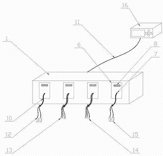
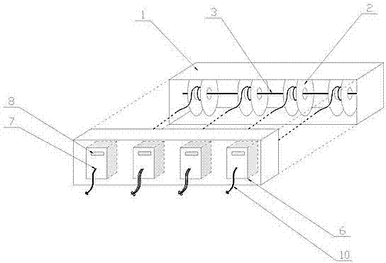
[0017] Such as figure 1 , 2 , shown in 3, same as prior art, there is the cable 11 that joins with electrocardiograph main frame 16, and cable 11 is respectively connected with two upper extremity clip-on probes 12, two lower extremity clip-on probes 15, the first group by signal line 10 The (three) chest suction cup probes 13 are connected to the second group (three) chest suction cup probes 14. The difference between embodiment 1 and the prior art is that a junction box body 1 is provided and fixed in the junction box 1. The four wire management ports 7 on the outer panel. The wire management ports 7 are through holes that are directly opened at the appropriate positions on the panel of the junction box body 1 and match the shape of the corresponding signal line 10. A shaft is fixed in the junction box body 1. 3. The reel 2 is slidingly connected with the shaft 3 through the shaft sleeve 21 integrated with it. The shaft 3 can be four shafts provided separately for each reel...

Embodiment 2

[0022] Such as Figure 4 , 5 , shown in 6, structure is basically the same as embodiment 1, difference is:

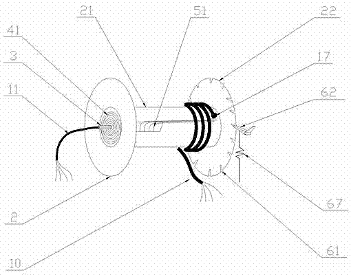
[0023] The driving device 4 of the reel 2 is a torsion spring 42 made of copper-plated or gold-plated steel wire, and the rotating jumper 5 is a copper-plated or gold-plated steel wire. The torsion springs 42 are fixed in the cavity formed between the shaft sleeve 21 of the reel 2 and the shaft 3, and the number is the same as the number of core wires of the corresponding signal lines 10. The torsion springs 42 are insulated from each other and arranged in a shielding arrangement. Copper or gold plating process Make sure it has high conductivity for signal transmission. The inner end of the torsion spring 42 is fixed to the shaft 3, the outer end of the torsion spring 42 is fixed to the axle sleeve 21 of the reel 2, and the two ends of the torsion spring 42 are respectively connected to the corresponding core wires of the signal line 10 and the cable 11.

[0024] The...

Embodiment 3

[0028] Such as Figure 7 Shown, structure is basically the same as embodiment 2, and difference is:

[0029] The rotating bridging device 5 is a transfer ring (or conductive bearing) 53 arranged in the cavity between the shaft sleeve 21 and the shaft 3 of the reel 2, the inner ring of the transfer ring 53 is fixed to the shaft 3, and the transfer ring 53 The outer ring of the wire reel 2 is fixed to the shaft sleeve 21 of the reel 2, and the inner ring and the outer ring of the power transfer ring 53 are slidably connected. And shielding arrangement and installation, the inner ring and the outer ring of the transfer ring 53 are respectively connected with the corresponding core wires of the cable 11 and the signal line 10 .

[0030] The reel driving device 4 of the reel 2 adopts a motor 43, and the motor 43 is connected with the reel 2 through gears. The wire harness locking control device 6 is composed of a wire take-up control button 8 and a control circuit.

[0031] The ...


PUM


Abstract

The invention discloses a wire harness coiling and decoiling device of an electrocardiograph, and the wire harness coiling and decoiling device is smooth in wire harness coiling and decoiling, is anti-winding, is convenient to operate and comprises a cable connected with an electrocardiograph host machine, wherein the cable is respectively connected with an upper limb clamping-type probe, a lower limb clamping-type probe, a first chest sucked type probe and a second chest sucked type probe by virtue of signal wires and is provided with a wire collecting box and a wire sorting port; the wire collecting box is internally provided with a wire coiling wheel capable of moving relative to the wire collecting box; the front end of the cable penetrates through and is fixedly arranged at the wire collecting box; the core wire of the cable is connected with the signal wire of which one end is fixedly arranged at the wire coiling wheel and wound on the wire coiling wheel and passes through the wire sorting port by virtue of a rotary crossover assembly; and the wire collecting box is internally provided with a wire coiling driving device provided with the wire coiling wheel and a wire harness locking control device.

Description

technical field [0001] The invention relates to an auxiliary device of medical equipment, in particular to a wire harness retractor for an electrocardiograph machine which can be retracted freely, is anti-winding, and is convenient to operate. Background technique [0002] As we all know, the electrocardiogram machine has become one of the most popular medical electronic equipment, which is used to record the physiological electrical signals generated when the heart beats, and provide a basis for clinical diagnosis. At present, the known electrocardiographs have a cable about 2 meters long that is respectively connected to the host computer and the junction box. After passing through the junction box, four groups of 0.8-1.2 meters long and a total of 10 signal lines (coaxial shielded wires) are separated. , and each group is respectively connected with two upper limb clip-on probes, two lower-limb clip-on probes, the first group (three) chest suction cup probes and the secon...

Claims


Application Information

Patent Timeline
Patent Type & Authority Applications(China)
IPC IPC(8): A61B5/0402
Inventor 刘雁春付建国王海亭
Owner 刘雁春
Why Eureka
Try Eureka