
Torsional oscillation damping device

A technology of attenuation device and torsional vibration, which is applied in the direction of vibration suppression adjustment, spring/shock absorber, mechanical drive clutch, etc., and can solve the problems of inability to increase the torsion angle of the hub and disc plate, clanging sound, cavity resonance attenuation, etc.

Inactive Publication Date: 2013-05-01
TOYOTA JIDOSHA KK
View PDF5 Cites 3 Cited by
  • Summary
  • Abstract
  • Description
  • Claims
  • Application Information

AI Technical Summary

Problems solved by technology

[0006] However, since this torsional vibration damping device has a structure in which the elastic members are arranged at equal intervals along the circumferential direction of the hub and the disc plate, the torsion angle of the hub and the disc plate cannot be increased, and the rattle, rattle, and vibration cannot be sufficiently suppressed. Cavity Resonance Attenuation

Method used


Image

  • Torsional oscillation damping device
  • Torsional oscillation damping device
  • Torsional oscillation damping device

Examples


no. 1 approach

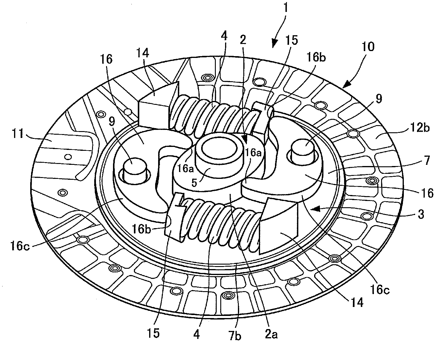
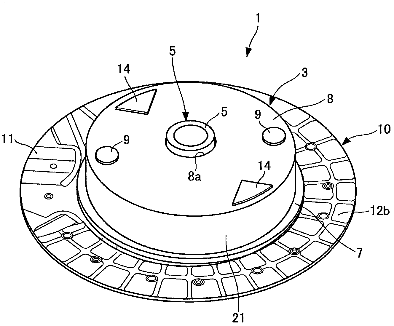
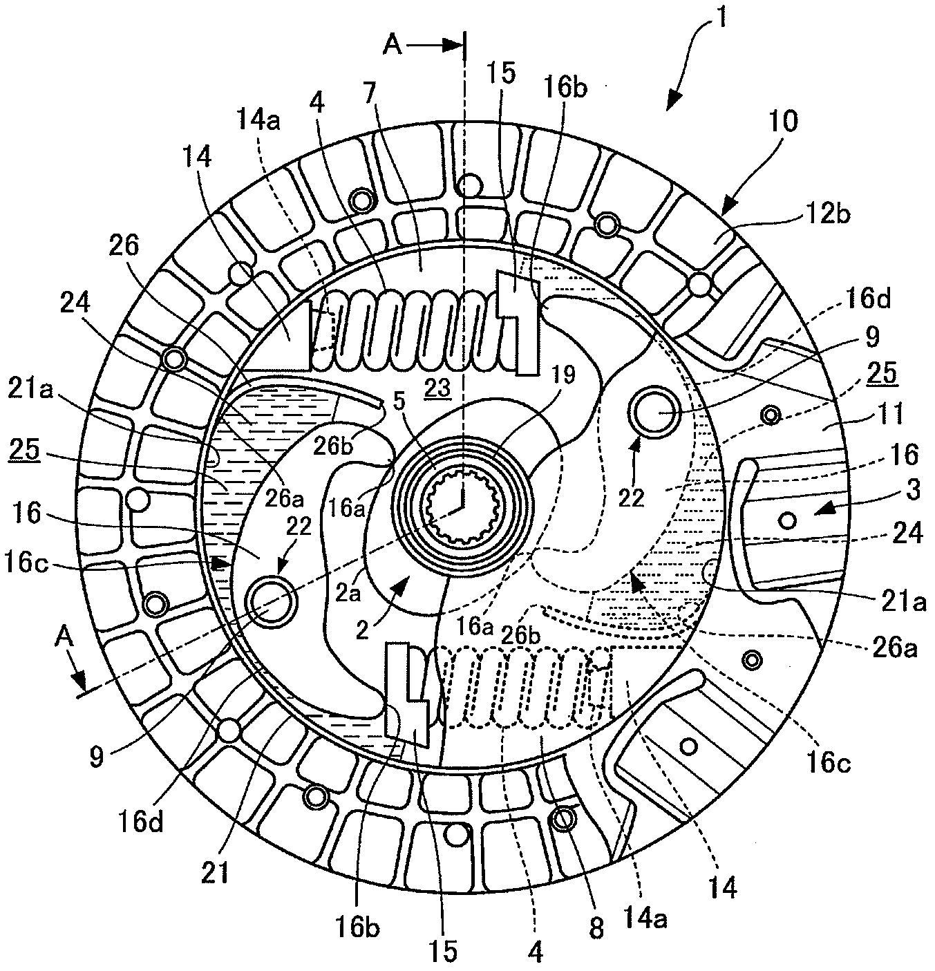
[0067] Figure 1 to Figure 8 It is a figure which shows 1st Embodiment of the torsional vibration damping apparatus of this invention.

[0068] First, the structure will be described.

[0069] exist Figure 1 to Figure 4 Among them, the torsional vibration damping device 1 includes a cam member 2 and a rotating member 3 provided on the same axis as the cam member 2 .

[0070] The rotary member 3 receives a rotational torque from an internal combustion engine (not shown) as a drive source, and the cam member 2 transmits the rotational torque of the rotary member 3 to a transmission of a drive transmission system (not shown).

[0071] A pair of coil springs 4 are provided between the cam member 2 and the rotating member 3 as elastic members, and the coil springs 4 are compressed when the cam member 2 and the rotating member 3 are relatively rotated.

[0072] The inner peripheral part of the cam member 2 is installed with the input shaft of the transmission of the drive transm...

no. 2 approach

[0169] Figure 9 , Figure 10 It is a figure which shows the 2nd Embodiment of the torsional vibration damping apparatus of this invention, The same code|symbol is attached|subjected to the same structure as 1st Embodiment, and description is abbreviate|omitted.

[0170] like Figure 9 As shown, a flexible bag body 30 is attached to the outer peripheral portion 16c of the arm member 16. The bag body 30 is made of, for example, a rubber or vinyl bag filled with a liquid such as silicone oil, and is freely compressible and deformable.

[0171] In this embodiment, if Figure 10 As shown, when the arm member 16 rotates in such a manner that the one end portion 16a of the arm member 16 moves from the inner side to the outer side in the radial direction along with the rotation of the cam member 2, the bag body 30 can be accommodated in the space while being compressed and deformed. Grease 24 in 25 is pressed out from space 25 reliably.

[0172] Therefore, the grease 24 can be re...

no. 3 approach

[0174] Figure 11 , Figure 12 It is a figure which shows the 3rd embodiment of the torsional vibration damping apparatus of this invention, and the same code|symbol is attached|subjected to the same structure as 1st Embodiment, and description is abbreviate|omitted.

[0175] like Figure 11 As shown, the inner peripheral portion 21a of the annular portion 21 is provided with a protrusion 41 integrally provided with the annular portion. It should be noted that the protruding portion 41 may be fixed to the inner peripheral portion 21 a of the annular portion 21 separately from the inner peripheral portion 21 a of the annular portion 21 .

[0176] This protrusion 41 constitutes a part of the annular portion 21 , and a radially inner peripheral portion (hereinafter simply referred to as an inner peripheral portion) 41 a of the protrusion 41 constitutes a part of the inner peripheral portion 21 a of the annular portion 21 .

[0177] In addition, the curved shape of the radially...


PUM


Abstract

In order to enable a lubricant to be supplied continuously to the contact area of one end of arm members and a cam surface, thus improving the lubrication capability at the contact area of the one end of the arm members and a cam member, and preventing wear, seizing and the like at the contact area of the one end of the arm members and the cam surface, a torsional oscillation damping device (1) has an annular part (21), which is attached to a disk plate (7) so as to surround a cam member (2) and arm members (16), and with which a portion of a grease (24) is held in the space between an inner circumferential part (21a) and the outer peripheral part of the arm members (16) in the radial direction when the grease (24) is scattered by centrifugal force and adheres to the inner circumferential part (21a) as the torsional oscillation damping device (1) rotates. Furthermore, the curved shape of the outer circumferential part (16c) of the arm members (16) is set with respect to the shape of the inner circumferential part (21a) of the annular part (21) such that when the arm members (16) turn so as to move one end part (16a) of the arm members (16) from the radially inward direction of the cam surface (2a) to the radially outward direction, the distance between the outer circumferential part (16c) of the arm members (16) and the inner circumferential part (21a) of the annular part (21) maintains a positional relationship wherein the distance increases gradually from the outer circumferential base point part (16d) of the arm members (16) toward the base end part (26a) of guide plates (26).

Description

technical field [0001] The present invention relates to a torsional vibration damping device, and more particularly relates to a device interposed between an internal combustion engine and a drive transmission system of a vehicle, and connecting a cam member and a rotating member via an arm member and an elastic member in order to transmit rotational torque between the cam member and the rotating member. Linked into a torsional vibration attenuation device that can rotate relatively freely. Background technique [0002] Conventionally, a drive source such as an internal combustion engine, an electric motor, and the like are connected to wheels through a drive transmission system including a transmission, and power is transmitted from the drive source to the wheels through the drive transmission system. However, the drive transmission system connected to the drive source, for example, generates cavity resonance and rattling noise due to torsional vibration whose vibration sou...

Claims


Application Information

Patent Timeline
Patent Type & Authority Applications(China)
IPC IPC(8): F16D13/64
CPCF16D13/74F16D13/64F16F1/00F16F2230/0064F16F15/1205
Inventor 日比野贵则
Owner TOYOTA JIDOSHA KK
Learn More