Core catcher having an integrated cooling path

A cooling channel and core capture technology, which is applied to cooling devices, reactors, nuclear power generation, etc., can solve the problems of prolonged core melt time, small channel cross-sectional area, and large channel resistance, etc., to achieve increased channel cross-sectional area, The effect of increased heat transfer area and reduced channel resistance

Active Publication Date: 2013-05-01
KOREA HYDRO & NUCLEAR POWER CO LTD +1
View PDF2 Cites 34 Cited by
  • Summary
  • Abstract
  • Description
  • Claims
  • Application Information

AI Technical Summary

Problems solved by technology

[0008] However, since the above-mentioned prior art core catcher is configured as a cooling pipeline form in which the cooling channels are separated from each other, the channel cross-section

Method used


Image

  • Core catcher having an integrated cooling path
  • Core catcher having an integrated cooling path
  • Core catcher having an integrated cooling path

Examples


Embodiment Construction

[0041] Hereinafter, the configuration and operation of preferred embodiments of the present invention will be described in detail with reference to the accompanying drawings.

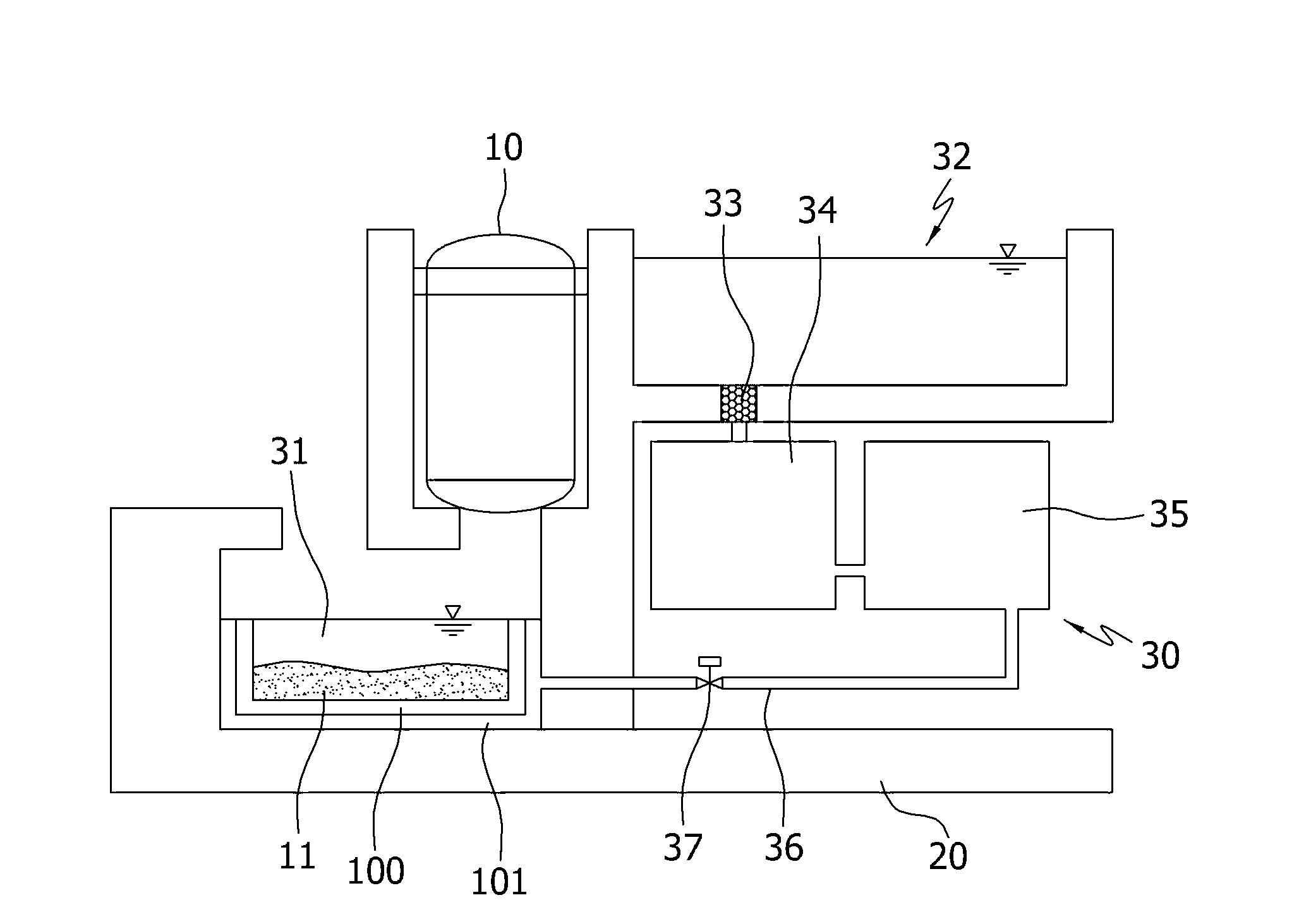
[0042] figure 1 It is a cross-sectional view schematically showing that the core catcher with integrated cooling channels according to the present invention is installed in the lower hole of the nuclear reactor building below the nuclear reactor pressure vessel.

[0043] According to the present invention, the core catcher 100 with integrated cooling channels is arranged in the lower hole of the nuclear reactor pressure vessel 10, so as to release the reactor core melt 11 released through the damaged part of the nuclear reactor pressure vessel 10 when a major accident occurs in the nuclear power plant. Stored and cooled to prevent interaction of said reactor core melt 11 with the pressure maintenance structures 20 of the nuclear reactor building.

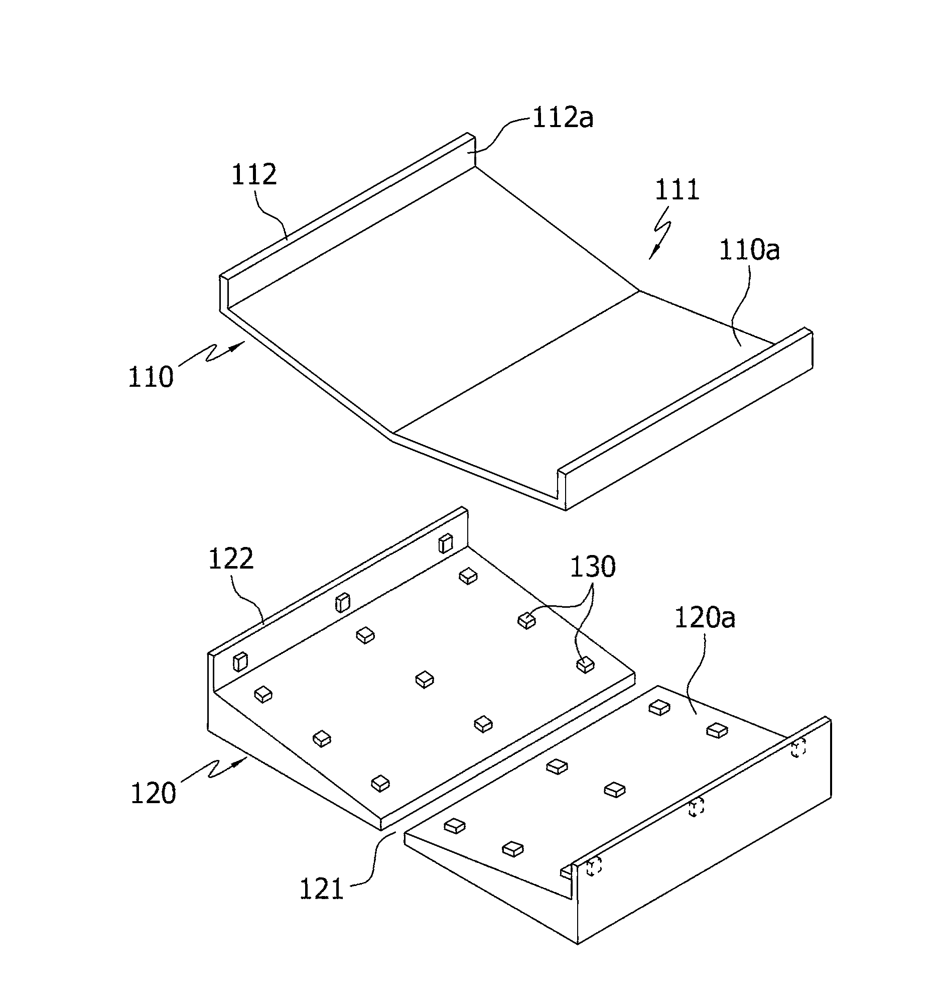
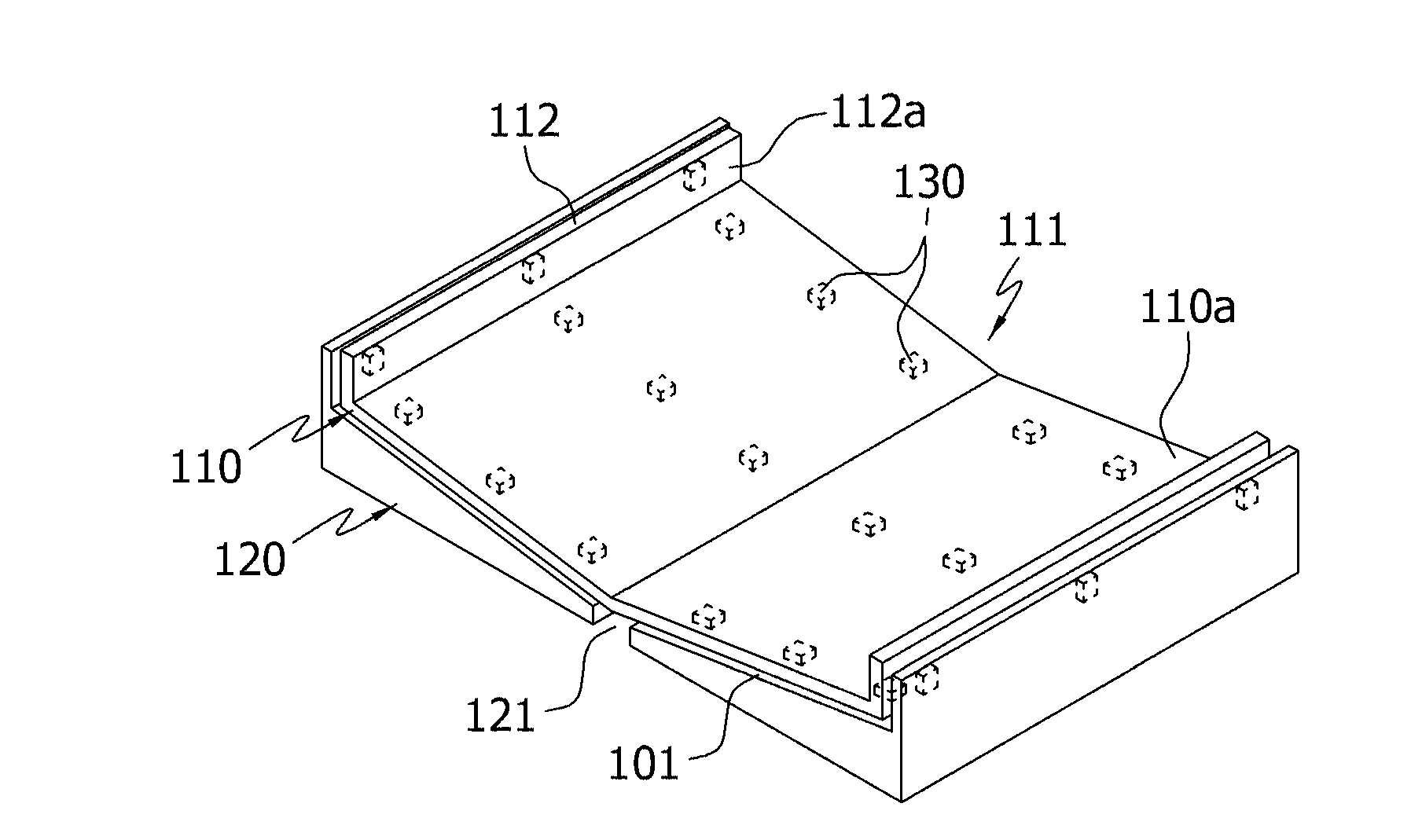
[0044] The core catcher 100 is formed in a container s...


PUM


Abstract

The object of the present invention is to provide a core catcher having an integrated cooling path, which comprises a structure able to effectively collect, retain and cool molten core material discharged through a damaged part of a nuclear reactor pressure container during a major incident in a nuclear power station. To this end, the present invention is a core catcher which is disposed underneath the nuclear reactor pressure container in order to retain and cool molten core material discharged through a damaged part of the nuclear reactor pressure container and prevent interaction between the molten core material and the pressure-holding structure of the reactor building during a major incident in the nuclear power station, and which comprises: a main container in the shape of an inverted roof which is provided underneath the nuclear reactor pressure container and collects the molten core material; and a lower structure which is disposed below and outside the main container with supports disposed at scattered points placed in between, thereby forming a cooling path having a predetermined spacing for eliminating the heat of the molten core material.

Description

technical field [0001] The present invention relates to a core catcher with integrated cooling passages, and more particularly to a reactor core melt that is released through the damaged part of the nuclear reactor pressure vessel by effectively collecting, storing and cooling the high-temperature reactor core when a major accident occurs in a nuclear power plant, so as to A core catcher with integrated cooling channels to maintain the robustness of the nuclear reactor building by preventing erosion caused by the interaction of the reactor core melt with the nuclear reactor building pressure holding structures. Background technique [0002] Although the possibility of occurrence is very small, when a major accident occurs in a nuclear power plant, there is a possibility that the reactor core melt will be released from the hole in the lower part of the nuclear reactor through the damaged part of the nuclear reactor pressure vessel. Here, the reactor core melt refers to a high...

Claims


Application Information

Patent Timeline
IPC IPC(8): G21C15/18G21C9/00
CPCG21C9/016Y02E30/40Y02E30/30
Inventor 金龙洙李钟镐许渲金志桓尹淳哲李羲道
Owner KOREA HYDRO & NUCLEAR POWER CO LTD
Why Eureka
Try Eureka