Centrifugal casting air discharging method for squirrel cage rotor and centrifugal casting die for implementing method

A squirrel-cage rotor and centrifugal casting technology, which is applied in the field of squirrel-cage rotors, can solve the problems of reduced motor energy conversion efficiency, broken ribs, entrained air bubbles, complex equipment structure, etc., to achieve improved efficiency, good compactness, and countercurrent effect small effect

Active Publication Date: 2013-05-08
HANGZHOU FUSHENG ELECTRICAL APPLIANCE
View PDF7 Cites 13 Cited by
  • Summary
  • Abstract
  • Description
  • Claims
  • Application Information

AI Technical Summary

Problems solved by technology

[0004] The present invention provides a squirrel-cage rotor centrifugal casting exhaust method capable of exhausting gas efficiently, conveniently and comprehensively, and a squirrel-cage rotor centrifugal casting mold for realizing the method, which solves the problems of the existing exhaust method and centrifugal casting mold casting In the case of cage rotors, there are problems of low production efficiency and complex equipment structure, or problems of poor density of the aluminum cage, broken ribs and entrained air bubbles, which lead to a decrease in the energy conversion efficiency of the motor

Method used


Image

  • Centrifugal casting air discharging method for squirrel cage rotor and centrifugal casting die for implementing method
  • Centrifugal casting air discharging method for squirrel cage rotor and centrifugal casting die for implementing method
  • Centrifugal casting air discharging method for squirrel cage rotor and centrifugal casting die for implementing method

Examples


Embodiment 1

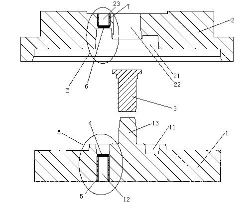
[0030] Embodiment one, see figure 1 , a squirrel-cage rotor centrifugal casting mold, comprising a lower mold 1, an upper mold 2 and a core 3.

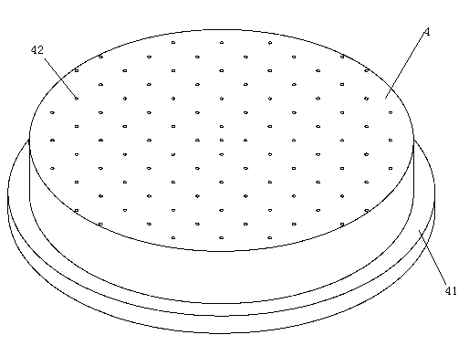
[0031] The lower mold 1 is provided with a ring cavity 11 at the lower end of the rotor. Seven lower installation through holes 12 are provided on the bottom wall of the rotor lower end ring cavity 11 . The lower mounting through holes 12 are evenly distributed along the circumferential direction of the rotor lower end ring cavity 11 . A lower exhaust mesh 4 and a lower exhaust mesh pressing rod 5 are arranged in the lower installation through hole 12 . The lower exhaust mesh pressing rod 5 is a tubular structure. The lower mold 1 is provided with a positioning mandrel 13 .

[0032] The upper mold 2 is provided with a rotor upper end ring cavity 21 and a casting hole 22 . Seven upper installation through holes 23 are provided on the bottom wall of the ring cavity 21 at the upper end of the rotor. The upper mounting through holes...

Embodiment 2

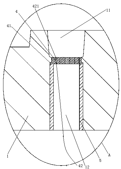
[0039] Embodiment two, the difference with embodiment one is: see Figure 7 , The lower mold 1 is provided with seven lower air extraction passages 14 . The inlet end 142 of each lower air extraction channel communicates with the lower installation through hole 12 respectively. The outlet end 141 of the lower air extraction channel is located on the radial side of the lower mold 1 . The curing section 421 of the lower vent hole is conical with a smaller opening area at the lower section and a larger opening area at the upper end. The opening area of ​​the upper port of the lower vent hole curing section 421 is 0.3 square millimeters. The lower exhaust mesh 4 is provided with a lower air cavity 43 . The air outlets of all the lower exhaust holes 42 on the same lower exhaust mesh communicate with the lower air cavity 43 . The lower air chamber 43 is provided with a lower air chamber air outlet 431 . The air outlet 431 of the lower air cavity is butted with the inlet end 142...


PUM


Abstract

The invention relates to a squirrel cage rotor. A squirrel cage rotor centrifugal casting die comprises an upper die and a lower die; the upper die is provided with a rotor upper end annular cavity; the lower die is provided with a rotor lower end annular cavity; the bottom wall of the rotor lower end annular cavity is provided with a plurality of lower air discharging holes of which opening areas are less than three square millimeters; and air is discharged by the lower air discharging holes in a casting process. The invention provides a centrifugal casting air discharging method for the squirrel cage rotor, and the squirrel cage rotor centrifugal casting die. By the method, air can be discharged efficiently, conveniently and comprehensively; and by the method and the die, the problems of low production efficiency and complex equipment structure, and the problem that energy conversion efficiency of a motor is reduced due to low compactness of an aluminum cage, broken ribs and air bubble entrainment in the conventional air discharging method and the process that the squirrel cage rotor is cast by the centrifugal casting die can be solved.

Description

technical field [0001] The invention relates to a squirrel-cage rotor, in particular to a centrifugal casting exhaust method for a squirrel-cage rotor and a centrifugal casting mold for realizing the method. Background technique [0002] The rotor is the rotating part of the motor. It is composed of rotor core, rotor winding and rotating shaft. Its function is to obtain the rotational torque under the action of the rotating magnetic field. The rotor is divided into a squirrel cage rotor and a wound rotor according to its structure. The squirrel-cage rotor consists of a rotor squirrel cage and a rotor core. The rotor squirrel cage is mainly composed of two types. One is to install copper bars in the slot holes of the rotor iron core, and the two ends are welded with rotor end rings to form a rotor squirrel cage shaped like a squirrel cage. The other is to use cast aluminum The way to form the rotor squirrel cage (aluminum cage is mainly used for small and medium-sized r...

Claims


Application Information

Patent Timeline
Patent Type & Authority Applications(China)
IPC IPC(8): B22D13/10H02K15/00H02K17/16
Inventor 葛明汪卫刚蒋利锋
Owner HANGZHOU FUSHENG ELECTRICAL APPLIANCE
Why Eureka
Try Eureka