Molten soup forging method and die thereof

A molten soup forging and mold technology, applied in the field of wheel forging, can solve problems such as damage to the center part of the wheel, difficult control of the amount used, affecting product quality, etc., to achieve the effect of improving pressure bearing capacity, avoiding side die misalignment, and improving product quality

Active Publication Date: 2013-05-08
TIANJIN NANUO MACHINERY MFG
View PDF7 Cites 5 Cited by
  • Summary
  • Abstract
  • Description
  • Claims
  • Application Information

AI Technical Summary

Problems solved by technology

At present, wheels are mainly produced by low-pressure casting. If the method of molten soup forging is applied to forged wheels, since the position of the center hole and bolt holes in the center of the wheel is the most important, if the pressure or impact force is concentrated, it may cause damage to the center of the wheel. The damage of the part, and the shrinkage cavity is more likely to occur at the inner center of the center bolt hole of the forged wheel
At present, the situation of shrinkage cavity can be solved by increasing the amount of melting soup, but the effect is not ideal, and the amount is not easy to control uniformly, resulting in waste of raw materials in production and high cost
[0003] The wheel mold is composed of an upper mold, a lower mold and multiple side molds. After the wheel is formed, the mold opening process is to lift the upper mold upwards and open the side molds to the surroundings. However, the pressure on the mold during the forging process is much greater than that of the casting, because the long-term During the forging process, the mold bears high pressure and is easy to be damaged. In addition, during the forging process, side die misalignment is prone to affect product quality, which poses unsafe hazards and high maintenance costs.

Method used


Image

  • Molten soup forging method and die thereof
  • Molten soup forging method and die thereof
  • Molten soup forging method and die thereof

Examples


Embodiment Construction

[0039]The present invention will be further described in detail below in conjunction with the accompanying drawings and through specific embodiments. The following embodiments are only descriptive, not restrictive, and cannot limit the protection scope of the present invention.

[0040] A molten soup forging method, the steps are as follows:

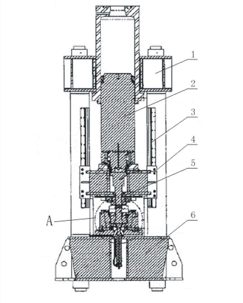
[0041] ⑴Mold preparation: the main oil cylinder of the forging machine drives the upper mold to rise to the top, and the lower mold returns to the working state, waiting for the molten soup to be injected;

[0042] (2) Molten soup injection: The ladle is driven by a special manipulator to scoop out the molten soup from the open heat preservation furnace. The amount of molten soup scooped is controlled by the solution height measuring device in the ladle. The manipulator moves and injects the molten soup into the mold of the lower mold. In the cavity, the molten soup is filled into the cavity of the lower mold under the action of gravity ...


PUM


Abstract

The invention relates to a molten soup forging method and a molten soup forging die. The molten soup forging method and the molten soup forging die comprise an upper die, a lower die and side dies, to-be-produced wheel-shaped die cavity is formed among the upper die, the lower die and the side dies, wherein the molten soup forging method and the molten soup forging die are characterized in that a lower die assembly formed by coaxially enclosing the plurality of side dies and the lower die is coaxially embedded in a pressure bearing die sleeve, and a hydraulic pressure lifting mechanism which is vertically upward and used for lifting products is coaxially arranged at the lower end of the lower die. The molten soup forging method and the molten soup forging die have the advantages of improving product quality, reducing molten soup dosage, improving inner structure refined grain of metals, improving product mechanical property, tensile property and other overall properties, shortening product production time, reducing equipment maintenance cost, increasing output, improving production efficiency and prolonging die service life.

Description

technical field [0001] The invention belongs to the field of wheel forging, in particular to a molten soup forging method and a mold thereof. Background technique [0002] Forging is a processing method that uses forging machinery to apply pressure to metal blanks to cause plastic deformation to obtain forgings with certain mechanical properties, certain shapes and sizes. Forging can eliminate defects such as as-cast porosity produced in the metal smelting process and optimize the microstructure. At the same time, due to the preservation of complete metal flow lines, the mechanical properties of forgings are generally better than castings of the same material. Casting types include: Gravity die casting, Low pressure die casting and Vacuum die casting. These casting methods tend to cause shrinkage cavity and gas ingress due to the slow solidification speed of the molten soup during production. The situation occurs, resulting in a product with a large difference in mechanical...

Claims


Application Information

Patent Timeline
Patent Type & Authority Applications(China)
IPC IPC(8): B22D18/02
Inventor 王显斌
Owner TIANJIN NANUO MACHINERY MFG
Why Eureka
Try Eureka