Polycrystalline silicon numerically controlled grinder

A technology for CNC grinding machines and polysilicon blocks, which is applied to grinding machines, machine tools suitable for grinding workpiece planes, and machine tools suitable for grinding workpiece edges, etc., which can solve difficult silicon square machining accuracy and accuracy stability and uncertainty Factors increase, increase the number of equipment requirements and other issues, to achieve the effect of reducing processing costs, good stability, and high efficiency

Inactive Publication Date: 2013-05-08
DALIAN LIANCHENG NUMERICAL CONTROL MACHINE
0 Cites 2 Cited by

AI-Extracted Technical Summary

Problems solved by technology

In addition, not only the processing efficiency is low, the chip removal condition is poor, but also due to factors such as repeated clamping of the silicon square, this increases the uncertainty factors in the processing process,...

Abstract

A polycrystalline silicon numerically controlled grinder comprises a machine base, grinding mechanisms and a movable screw rod which is arranged in the longitudinal direction. A screw nut which fits in with the movable screw rod is arranged in a screw nut seat through an axletree. The screw nut is connected with an output end of a movable motor through a transmission mechanism. The movable motor is fixed on the screw nut seat. A movable sliding table is fixedly connected with the screw nut seat. The movable sliding table is connected with the machine base in a sliding mode. A clamp body is connected with the movable sliding table. A left clamp head body is fixedly connected with the left end of the clamp body. The clamp body is provided with a clamping screw rod in a supporting mode. The clamping screw rod is connected with an output shaft of a clamping motor. A clamping screw nut which fits in with the clamping screw rod is connected with a right clamp head body. A left clamp head is connected with the left clamp head body in a rotating mode. A right clamp head is connected with the right clamp head body in the rotating mode. The left clamp head is connected with a rotating mechanism. The polycrystalline silicon numerically controlled grinder has the advantages of being simple in whole structure, flexible and reliable in movement, high in efficiency, accurate in size controlling, good in stability, and capable of reducing machining cost due to the fact that two groups of opposite side faces and chamfers of a workpiece are grinded after the workpiece is clamped once.

Application Domain

Technology Topic

Image

  • Polycrystalline silicon numerically controlled grinder
  • Polycrystalline silicon numerically controlled grinder

Examples

  • Experimental program(1)

Example Embodiment

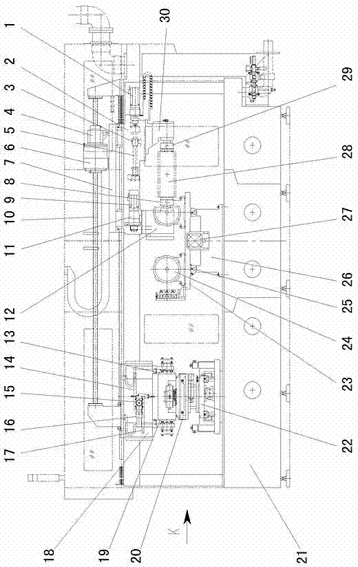
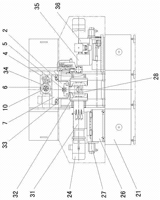
[0013] like figure 1 , 2 Shown: 21 is machine base, and the middle part of machine base 21 is positioned at the front side and rear side horizontally and is respectively provided with symmetrical two pairs of totally four groups of grinding mechanisms, and grinding mechanism is arranged on the grinding slide 23. The grinding mechanism includes a grinding spindle 31 fixed on the grinding slide 23. The input shaft of the grinding spindle 31 is connected to the grinding motor 24, and the output shaft end is equipped with a grinding disc 32, which is a disc-shaped grinding wheel. The end of the motor 24 is fixedly connected with the end of the grinding spindle 31 by bolts.
[0014] The grinding slide 23 is located on the grinding track 25 through the slider below it, the grinding track 25 is fixed on the grinding seat 26, the grinding seat 26 is fixedly connected with the machine base 21, and the grinding slide 23 is connected to the grinding track 25. A screw nut driving mechanism connected with the grinding feed motor 27 is arranged between the seats 26 . The grinding feed motor 27 can drive the grinding slide 23 to move laterally relative to the support 21 through the screw nut when the grinding feed motor 27 is in action.
[0015] Vertically above the support 21, a moving screw 10 is supported by a bracket, and the screw nut matched with the moving screw 10 is installed in the screw nut seat 6 through a bearing and is connected with the output shaft of the moving motor 4 by a transmission belt 34, and the moving motor 4 Be fixed on the silk female seat 6.
[0016] A mobile slide 7 is fixedly connected to the silk female base 6, and the mobile slide 7 is slidingly connected to the machine base 21, that is, the mobile slide 7 is located on the mobile slide rail 33 fixedly connected to the machine base 21 through a slider. The mobile slide table 7 and the machine base 21 also can adopt the linear guide rail mode to be connected. The mobile slide table 7 is fixedly connected with the clamp body 2, and the left end of the clamp body 2 is fixedly connected with the left chuck body 12. The clamping body 2 is supported by a clamping screw 5 through a connecting frame, the clamping screw 5 is connected to the output shaft of the clamping motor 1 , and the clamping motor 1 is fixed on the clamping body 2 . The clamping nut 3 matched with the clamping screw 5 is fixedly connected with the right chuck body 30, the clamping motor 1 can drive the clamping screw 5 to rotate, and the right chuck body 30 is driven by the clamping nut 3 to move. The left chuck body 12 and the right chuck body 30 are respectively connected with the left chuck 8 and the right chuck 29 through rotating shafts.
[0017] The rotating shaft of left chuck 8 joins with rotation speed reducer 11 by transmission belt mechanism, and rotation speed reducer 11 joins with the rotating motor 9 that is fixed on the chuck body 2.
[0018] The left part of the machine base 21 is equipped with a workpiece size detection mechanism and a workpiece positioning centering mechanism, including a conveying slide 22 connected to the machine base 21 through a linear track, and a workpiece height and width detection, The positioning mechanism 20, the workpiece is clamped by the rear width inspection clamping body 35 and the front width inspection clamping body 36 and the size and height of the opposite two sides of the workpiece can be known by taking out the signal through the sensor, wherein the rear width inspection clamping body 35 And front wide inspection clamping body 36 has one and conveying slide table 22 and can slide relatively and connect drive mechanism. Above the height and width detection and positioning mechanism 20, there is a workpiece length detection and centering mechanism, including a support plate 38 fixed on the machine base 21, a reducer is installed on the support plate 38, and the detection motor 16 and the input end of the reducer connection, the output end of the reducer is connected to the gear 15, the vertical slide 18 is connected to the support plate 36 through a linear guide rail, and the upper rack 14 and the lower rack 17 are installed on the vertical slide 18, between the two rack ends and the vertical Fixed connection vertical slide plate 18 is connected with right clamping plate 13 and left clamping plate 19 by connecting plate, detection motor 16 can drive gear 15 to rotate, drives upper rack 14 and lower rack 17 to move simultaneously, thereby drives left clamping plate 19 and right clamping plate 13 can Relatively move, clamp both ends of the workpiece, understand the length of the workpiece through the encoder and system calculation, and automatically adjust the center of the workpiece.
[0019] Each motor mentioned above is connected with the electric control device,
[0020] The working process is: manually send the workpiece 28 to the size detection mechanism and the workpiece positioning and centering mechanism, detect the width of the workpiece, and transport it to the centering mechanism by the conveying slide 22, and then detect the height and length of the workpiece and adjust them. middle. Transported by the conveying slide 22 to the clamping (place) position in the machine tool (the fixture has been moved here to wait), the moving motor 4 drives the nut in the nut seat 6 to rotate, and the nut seat 6 moves along the moving screw 10 at the same time, Drive the moving slide table 7, the chuck body 2, the left chuck body 12 and the left chuck 8 to approach the left end of the workpiece 28 (left end displacement), and then the right chuck body 30 and the right chuck 29 are clamped by the action of the clamping motor 1 Workpiece 28 (push right end). Then it moves to the grinding area, and the detection device 37 is driven by the grinding slide 23 to detect the opposite side of the workpiece. Through the calculation and allocation of grinding times (surplus) by the system, the action of the grinding motor 24 can drive the grinding disc 32 to rotate, and at the same time grind (grinding is divided into coarse and fine) a pair of sides of the workpiece, and the other pair of sides drives the left side through the rotating motor 9. Grinding after chuck 8, workpiece 28, right chuck 29 rotates, the chamfering of workpiece 28 and relative side detection are also detection or grinding after determining the position by means of rotation.
[0021] The overall structure is simple, the action is flexible and reliable, the efficiency is high, the size control is accurate, and the stability is good. After the workpiece is clamped once, the two sets of opposite sides and chamfers of the workpiece can be ground, which reduces the processing cost.

PUM

no PUM

Description & Claims & Application Information

We can also present the details of the Description, Claims and Application information to help users get a comprehensive understanding of the technical details of the patent, such as background art, summary of invention, brief description of drawings, description of embodiments, and other original content. On the other hand, users can also determine the specific scope of protection of the technology through the list of claims; as well as understand the changes in the life cycle of the technology with the presentation of the patent timeline. Login to view more.

Similar technology patents

Integrated embedded pipe hot stamping die for automobile parts

InactiveCN102029310AManufacturing process cycle and cost reductionThe overall structure is simpleShaping toolsMotor vehicle partHot stamping
Owner:BAOSHAN IRON & STEEL CO LTD

Classification and recommendation of technical efficacy words

  • The overall structure is simple
  • Flexible and reliable

Time frequency analysis based loudspeaker noise online detecting instrument

InactiveCN101115329AThe overall structure is simpleLow installation and manufacturing costsElectrical apparatusTime–frequency analysisLoudspeaker
Owner:TIANJIN UNIVERSITY OF SCIENCE AND TECHNOLOGY +1

Stretcher compartment

ActiveCN102961221ASimple structureFlexible and reliableAmbulance serviceDrive motorEngineering
Owner:JIANGSU RIXIN MEDICAL EQUIP

Small-end connected selection equipment for convenient chopsticks

Owner:营口经济技术开发区明成实业有限公司

Film cutoff device

Owner:大连橡胶塑料机械有限公司
Why Eureka
Try Eureka