Deburring machine tool

A deburring and machine tool technology, which is applied to grinding machines, machine tools suitable for grinding the edge of workpieces, metal processing equipment, etc., can solve the problems of hidden dangers to life and property, scattered processes, low production efficiency, etc., and achieve thorough deburring and simple operation , design reasonable effect

Active Publication Date: 2013-05-08
江苏瑞普机床有限公司
View PDF5 Cites 12 Cited by
  • Summary
  • Abstract
  • Description
  • Claims
  • Application Information

AI Technical Summary

Problems solved by technology

[0003] At present, the deburring of such parts is mainly performed manually by operators holding steel brushes. Due to the large output of products, high labor intensity of employees, unsatisfactory deburring, low production efficiency, scattered processes, and often missing processing, etc., for Removing the clean burr residue will affect the cleanliness index of even parts, and will cause problems such as stuck parts, which will eventually affect the normal operation of the internal combustion engine, which will seriously cause traffic accidents and bring huge losses to people's lives and property. Hidden danger

Method used


Image

  • Deburring machine tool
  • Deburring machine tool
  • Deburring machine tool

Examples


Embodiment Construction

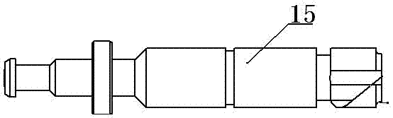
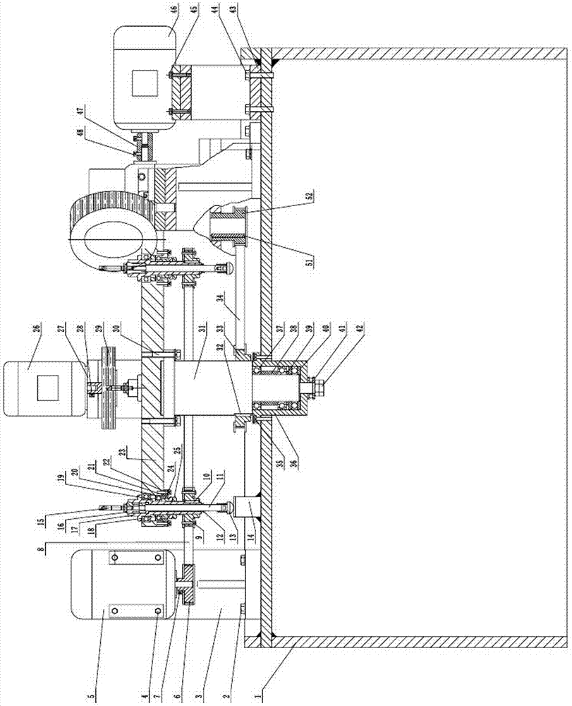
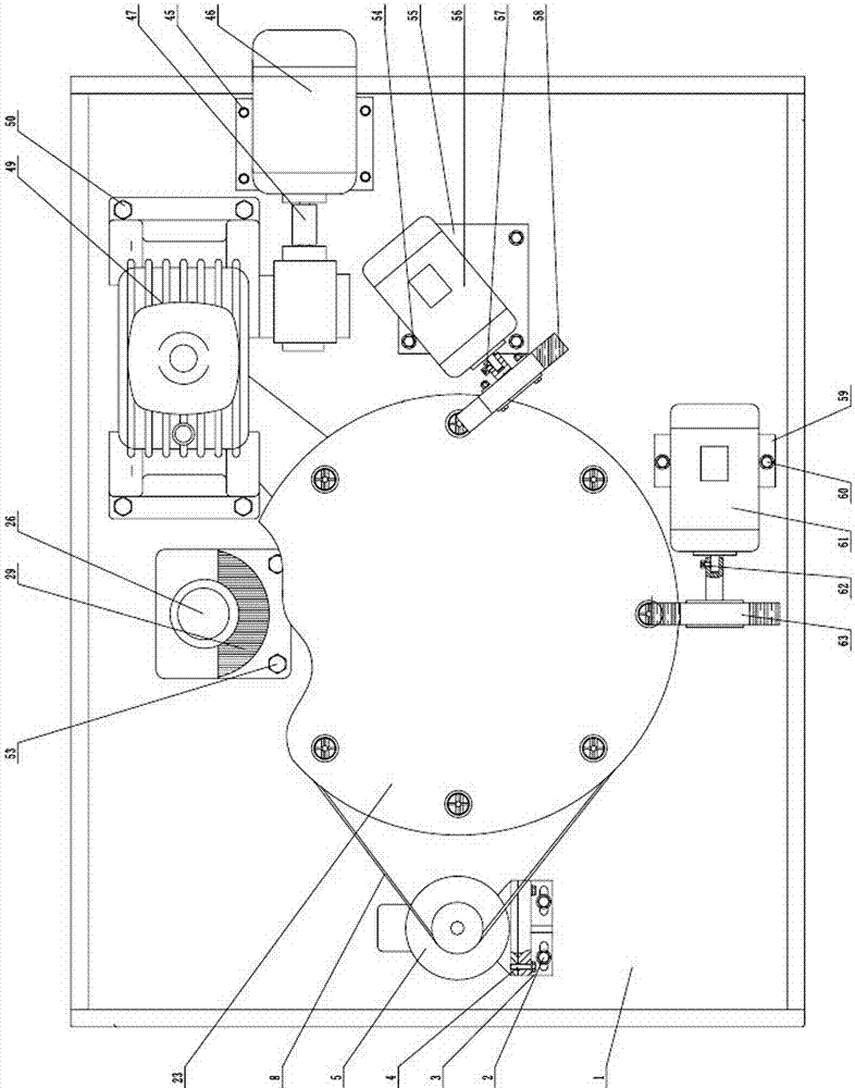
[0015] Refer to attached Figure 1~3 , The deburring machine tool includes bed 1, outer hexagon bolt 1 2, fixture transmission motor seat 3, outer hexagon bolt 2 4, micro motor 1 5, fixture driving pulley 6, hexagon socket head screw 1 7, timing belt 8 , Fixture driven pulley 9, flat key one 10, pull rod 11, compression spring one 12, very block 13, chuck top block 14, elastic chuck 16, elastic chuck seat 17, plane bearing one 18, spacer ring 19, Deep groove ball bearing 120, lower end cover 21, hexagon socket head screw 222, rotary disc 23, bushing 24, joint cap 25, micro motor 26, horizontal motor bracket 27, hexagon socket head screw 3 28, disc Type steel brush 1 29, outer hexagon bolt 3 30, main shaft 31, flat key 2 32, main shaft pulley 33, timing belt 2 34, hexagon socket head screw 4 35, bearing seat 36, deep groove ball bearing 2 37, bushing 38. Spacer ring 39, plane bearing 2 40, plane bearing 3 41, nut 42, main motor bracket 43, outer hexagon bolt 4 44, outer hexago...


PUM


Abstract

The invention discloses a deburring machine tool which relates to an excricle deburring machine tool of shaft parts, in particular to a machine tool used for deburring a straight flute, a transverse groove, a chute of an excircle of a pillar plunger core inside a plunger and barrel assembly. The deburring machine tool comprises a machine body, a fixture drive motor seat, a first micro motor, a fixture driving pulley, a first synchronous belt, a fixture driven pulley, a first flat key, a draw bar, a first compression spring, a supporting block, a clamping head top block, an elastic clamping head, an elastic clamping head seat, a first plane bearing, a space ring, a first deep groove ball bearing, a lower end cover, a rotary disk, a bush, a combination cap, a second micro motor, a horizontal motor support, a first disk type steel brush, a main shaft, a second flat key, a main shaft belt pulley, a second synchronous belt, a bearing seat, a second deep groove ball bearing, a bush, a space ring, a second plane bearing, a third plane bearing, a nut, a main motor support, a third micro motor, a coupler, a reduction box, a second flat key, a driving pulley, an inclined motor seat, a fourth micro motor, a second disk type steel brush, a vertical motor seat, a ninth outer hexagon bolt, a fifth micro motor and a third disk type steel brush.

Description

technical field [0001] The invention relates to a machine tool for deburring shaft parts, in particular to a machine tool for removing burrs from straight grooves, horizontal grooves or inclined grooves on the outer circle of a plunger core in a plunger pair. Background technique [0002] The plunger core of the internal combustion engine fuel injection pump is made of Cr12MoV and the hardness range is HRC60-65. The straight groove, horizontal groove or inclined groove on the plunger core in the plunger couple of the internal combustion engine controls the amount of oil input to the internal combustion engine and plays the role of oil distribution. (see attached figure 1 ) [0003] At present, the deburring of such parts is mainly performed manually by operators holding steel brushes. Due to the large output of products, high labor intensity of employees, unsatisfactory deburring, low production efficiency, scattered processes, and often missing processing, etc., for Remo...

Claims


Application Information

Patent Timeline
IPC IPC(8): B24B9/00
Inventor 伍永刚金伟岳齐
Owner 江苏瑞普机床有限公司
Why Eureka
Try Eureka