Concrete vertical conveying pouring system

A vertical transportation and concrete technology, applied in construction, infrastructure engineering and other directions, can solve the problems of aggregate separation, difficult pipe dismantling, long time, etc., and achieve the effect of shortening construction period, reducing construction cost and convenient installation.

Active Publication Date: 2013-05-08
河南省水利第二工程局集团有限公司 +1
View PDF7 Cites 4 Cited by
  • Summary
  • Abstract
  • Description
  • Claims
  • Application Information

AI Technical Summary

Problems solved by technology

[0003] If the pumping scheme is adopted, it will not be able to meet the requirements for cracking due to the large amount of glue used in pumping concrete, high heat of hydration, small coarse aggregate particles, and large shrinkage ratio; the pumping construction capacity is limited, and the construction strength cannot be met. If the pipe is blocked, it will be difficult to dismantle the pipe and take a long time. It is difficult to ensure that there will be no cold cracks in the concrete, which will affect the quality of the project entity; the cost of pumping concrete is high
[0004] With the tower belt machine scheme, it is necessary to arrange the mixing station, belt conveyor and tower belt machine together, but it is impossible to build a mixing station in a small place. Machine advantage
[0005] The "Concrete Transportation System" of Chinese Patent Application No. CN101956557A discloses a concrete transportation system, including a mixing station, a dispatching winch, a bottom unloading bucket, a suspension pan and an ash separator. During transportation, under the action of gravity, there will be a problem of aggregate separation

Method used


Image

  • Concrete vertical conveying pouring system
  • Concrete vertical conveying pouring system
  • Concrete vertical conveying pouring system

Examples


Embodiment Construction

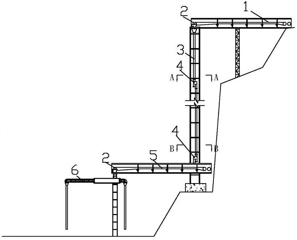
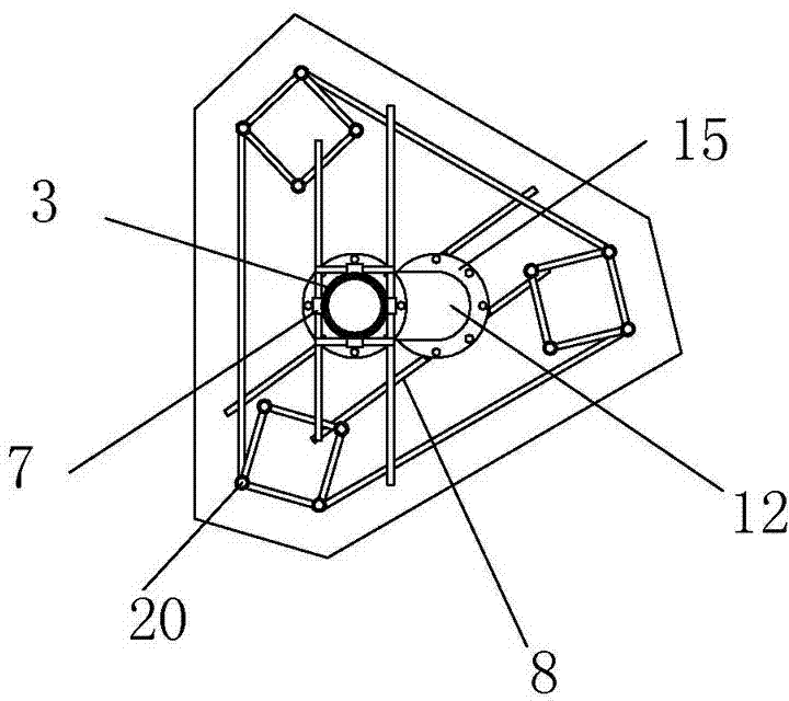
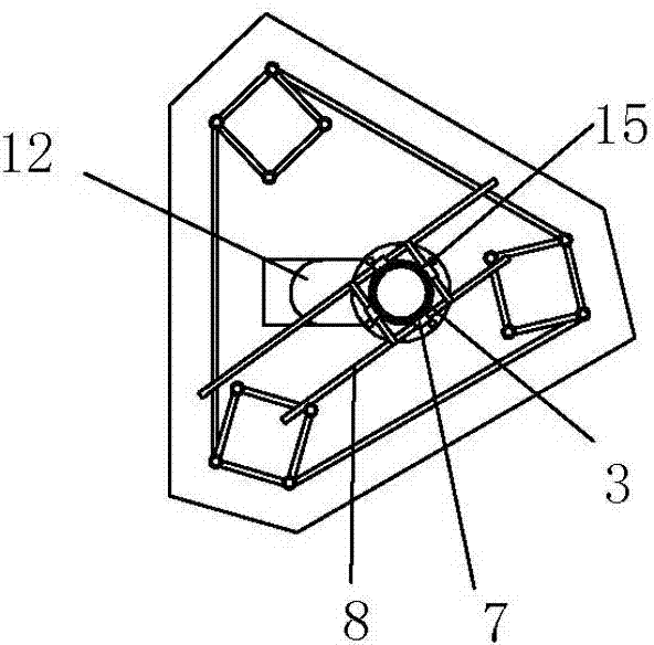
[0033] see Figure 1 to Figure 10 , the first belt conveyor 1 is erected next to the construction road for horizontal transportation, the output end is placed above the upper inlet of the vertically placed box pipe, the concrete is transported vertically through the vertically arranged box pipe 3, and the second belt is erected at the lower end of the box pipe 3 The machine 5 conveys the concrete to the concrete distribution machine 6, and the second belt conveyor 5 is placed on the top of the concrete distribution machine 6 in a horizontal position of 360 0 The elephant trunk slide pipe of diameter 420mm hangs at 6 two ends of the concrete distributing machine that rotates and carries out storehouse surface distributing.

[0034] The Box pipe 3 has a single section length of 6m and a wall thickness of 10mm, and is installed on an equilateral triangular support composed of three steel cylinders 20 with a side length of 1.0m. The lower part of the bracket is fixed with C25 c...


PUM


Abstract

The invention discloses a concrete vertical conveying pouring system which is applied to a vertical high fall concrete conveying scheme. The concrete vertical conveying pouring system comprises a belt conveyor, a box pipe and a concrete distributing machine. An output end of the horizontally arranged first belt conveyor is arranged above an inlet at the upper portion of the box pipe which is vertically arranged, an outlet at the lower portion of the box pipe is arranged above an input end of a second belt conveyor which is horizontally arranged, an output end of the second belt conveyor is connected with the concrete distributing machine, chutes are arranged at tow ends of the concrete distributing machine, and a descent control device is respectively arranged on the outlet at the lower portion of the box pipe and an outlet in the middle of the box pipe. In the vertical conveying process of the concrete with high fall and high slope, the concrete vertical conveying pouring system avoids aggregate separation caused by free falling of the concrete on one hand, and avoids severe damage caused by the belt conveyor below a pipe wall and a pipe caused by high fall on the other hand. Aggregate in the pipeline cannot freely fall off, and the aggregate can be in a fluid state, flowing in the pipeline equals to secondary blending, so that the concrete is evenly mixed.

Description

technical field [0001] The invention relates to a concrete vertical transport pouring system, which is suitable for the vertical high-drop concrete transport scheme in water conservancy projects. Background technique [0002] After the concrete clinker comes out of the mixing system, it is transported horizontally and vertically to the pouring work surface. For horizontal transportation, bucket trucks or tank trucks are generally used for small and medium-sized projects, and tank trucks, dump trucks or belt conveyors are generally used for large-scale projects; for vertical transportation , Small and medium-sized projects generally use chutes, manual overturning, truck cranes, conveying pumps, etc., and large-scale projects generally use tower cranes, gantry cranes, tower belt conveyors and cable cranes. [0003] If the pumping scheme is adopted, it will not be able to meet the requirements for cracking due to the large amount of glue used in pumping concrete, high heat of h...

Claims


Application Information

Patent Timeline
Patent Type & Authority Applications(China)
IPC IPC(8): E02D15/02
Inventor 甘继胜赵长伟程昌建职轶李文莉常婕王为然翟春明陈尊王资换王茹司马军程瑞芳李凌湧王旭明
Owner 河南省水利第二工程局集团有限公司
Why Eureka
Try Eureka