
Channelized LED (light-emitting diode) lamp

An LED lamp and channel-type technology, which is applied in the cooling/heating device of lighting devices, lighting devices, light sources, etc., can solve the problems of heat dissipation of LED lights, the heat dissipation effect of dust accumulation in the heat sink, and the high cost of waste of aluminum alloy materials.

Inactive Publication Date: 2013-05-08
潘忠勋
View PDF0 Cites 14 Cited by
  • Summary
  • Abstract
  • Description
  • Claims
  • Application Information

AI Technical Summary

Problems solved by technology

[0004] The key point of the present invention is to solve the heat dissipation problem of existing LED lamps, and it uses a simple and easy scientific method to solve this difficult problem
[0005] The second purpose of the present invention is to solve the problem of high waste cost of existing LED lamp aluminum alloy materials, energy saving, waste, and environmental protection must outweigh the gains, so that the product can truly achieve the effects of low carbon, energy saving, and environmental protection, and Inexpensive
[0006] The third purpose of the present invention is to solve the problem that the heat dissipation effect of the LED lamp in the prior art is affected by the accumulation of dust in the heat sink over time

Method used

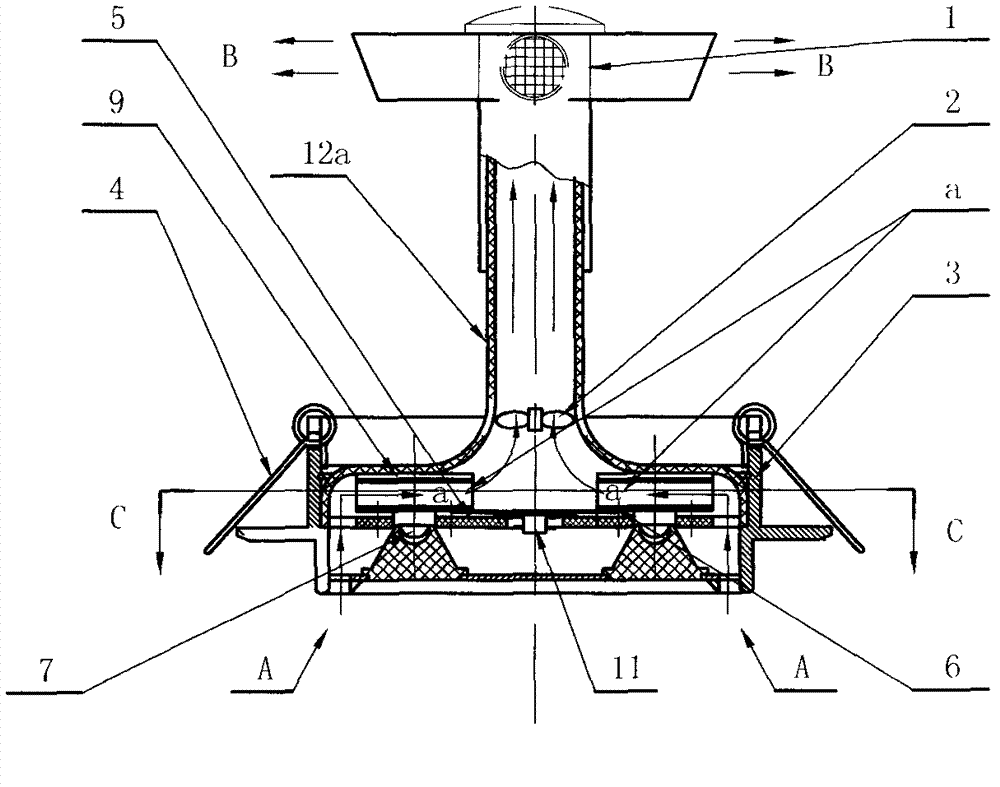
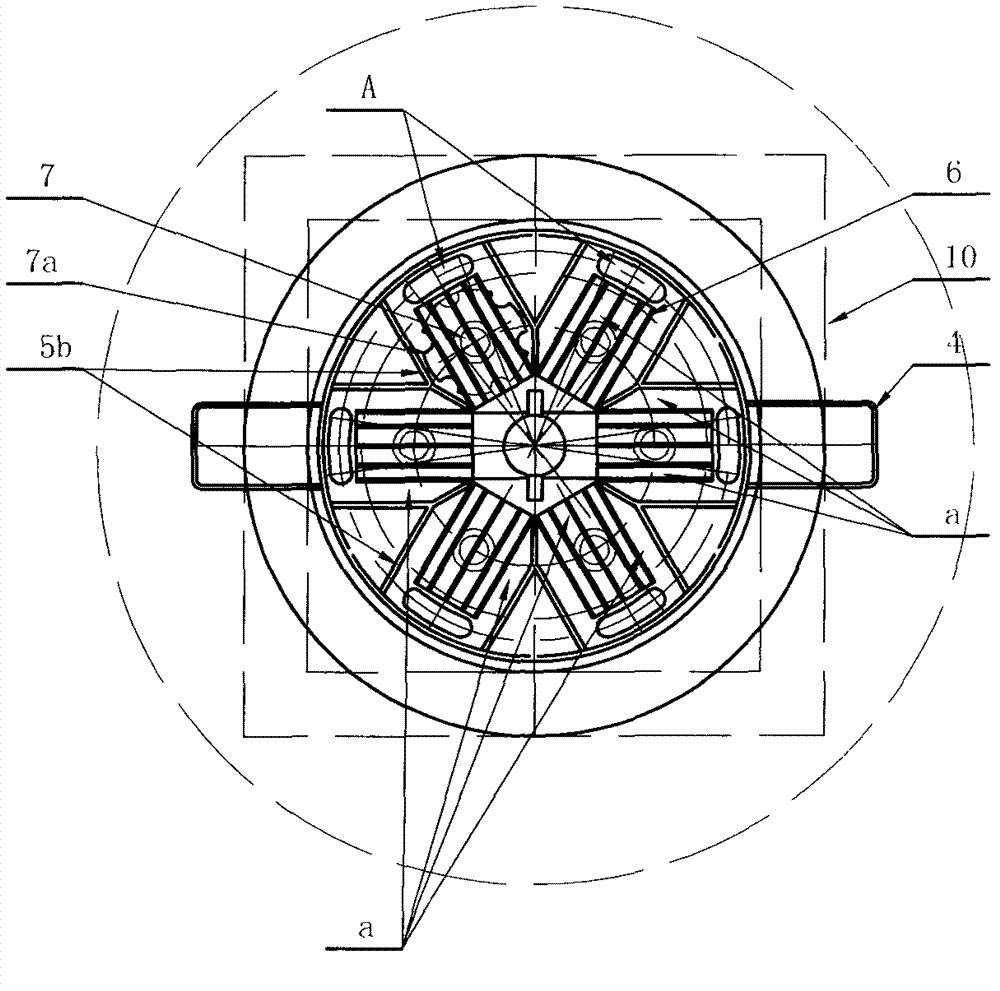
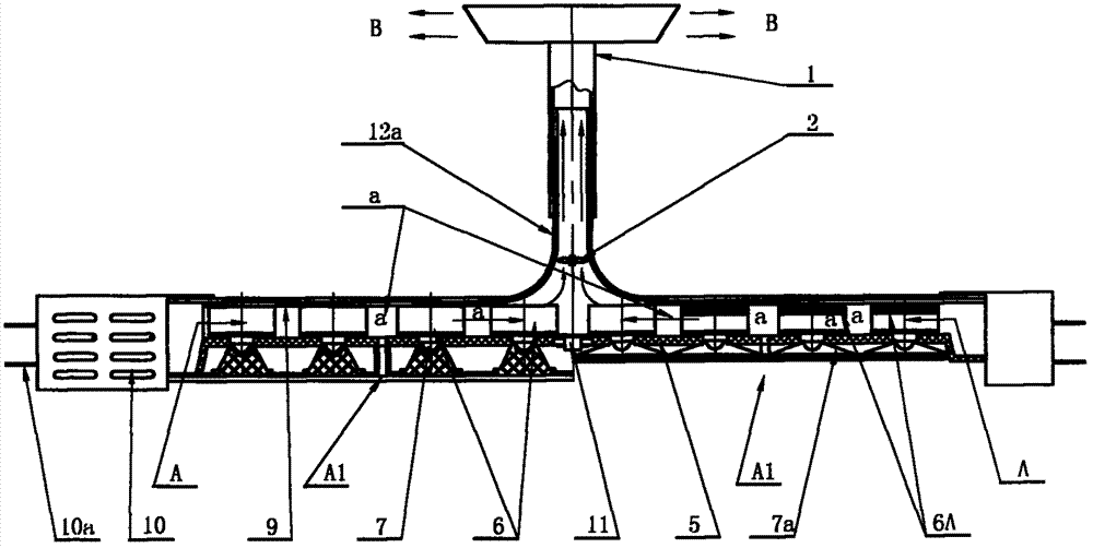

Image

  • Channelized LED (light-emitting diode) lamp
  • Channelized LED (light-emitting diode) lamp
  • Channelized LED (light-emitting diode) lamp

Examples


Embodiment Construction

[0032] In order to further understand structure of the present invention, describe as follows with reference to accompanying drawing:

[0033] refer to figure 1 , 2 , is a channel-type LED lamp embodiment 1. It is a ceiling lamp. An inverted "T"-shaped middle air outlet 12a is installed in the lamp support 3. There are heat-conducting fins 6 on the left and right inside the lower part, and the lower part of the heat-conducting fin 6 is Adhering to the LED lamp chip 7, and fixedly connected with the support plate 5 through the screw holes on the heat conduction sheet 6, the heat conduction sheet 6 (group), the whole structure is reduced and distributed on the support plate 5, and the narrow channels of several airflow partition ribs 5a In a, the lower part of the left and right ends of the heat conduction sheet 6 (group) communicates with the air inlet A, and a T-shaped air outlet pipe 1 is installed in the middle air outlet 12a. , and according to the power of the LED lamp a...


PUM


Abstract

The service life of a traditional LED (light-emitting diode) lamp can be directly affected by heat dissipation effect of chips, and accordingly a larger aluminum alloy cooling fin is arranged on the top of the LED lamp so as to reduce the temperature by air circulation. When the power of the LED lamp becomes larger, the size of the aluminum alloy cooling fin increases to dissipate the heat by air circulation. According to this arrangement, the heat dissipation effect is affected in harsh and hot climate and the cost of the larger aluminum alloy cooling fin is high. By means of utilizing diverse physical phenomena and reverse thinking, the channelized LED lamp is capable of gathering the heat in narrow channels so as to enable the heat produced rapidly to cause temperature difference and air circulation. Due to setting temperature limitation, the wind can be blown out frequently and heat dissipation effect is consistent in high-temperature regions and hot weather. The channelized LED lamp is simple and scientific in structure and the aim of natural ventilation can be achieved by the gas flue effect without the huge cooling fin. Accordingly, a large number of aluminum alloy materials can be saved, the low-cost, low-carbon, energy-saving and environment-protection effect of the channelized LED lamp can be achieved and the country and the people can benefit from the channelized LED lamp.

Description

technical field [0001] The invention belongs to the lighting industry Background technique [0002] In the previous LED lights and chip heat dissipation problem is a technical focus, if the heat dissipation is not good, it will directly affect the life of the LED street lamp, at the slightest, it will accelerate the light decay and shorten the life of the LED light, and at the worst, it will burn the chip and the LED bulb, so the upper part of the LED street light There is a large aluminum alloy die-cast heat sink to reduce the temperature. The greater the power of the LED, the larger the heat dissipation "hat". They all use the size of the aluminum alloy heat sink to dissipate heat. The rise of temperature causes air convection to dissipate heat in the air, and also uses atmospheric flow to dissipate heat. This structure affects the heat dissipation effect in harsh hot weather environments. The larger the heat sink, the higher the cost, and the smaller the shortened LED lam...

Claims


Application Information

Patent Timeline
Patent Type & Authority Applications(China)
IPC IPC(8): F21V29/02F21Y101/02F21V29/67F21V29/83
Inventor 潘忠勋潘战海潘战宇
Owner 潘忠勋
Learn More