
360-degree stress monitoring optical fiber grating microbend sensor

A microbend sensor and fiber grating technology, which is applied in the direction of force measurement by measuring the change of optical properties of materials when they are stressed, can solve the problems of limiting sensitivity and long design of toothed plate size, and achieves high sensitivity. Effect

Inactive Publication Date: 2013-05-08
HUAZHONG UNIV OF SCI & TECH
View PDF4 Cites 10 Cited by
  • Summary
  • Abstract
  • Description
  • Claims
  • Application Information

AI Technical Summary

Problems solved by technology

[0003] There are many types of fiber grating micro-bending sensor structures, such as corrugated, zigzag, spiral, elastic cylinder or cylinder, cross-frame, etc. Usually, the zigzag structure is used more, and the structure of this kind of structure The sensitivity depends on the length of the micro-bent fiber grating between the toothed plates and the distance between the tooth grooves. By rationally designing the space between the tooth grooves, the bending of the fiber grating can achieve the best effect and improve the sensitivity, but the size of the toothed plates is impossible The design is very long, which ultimately limits the sensitivity of this structure
Most of the sensors in the above structural types can only measure changes in external parameters such as stress, displacement, and acceleration in a specific orientation. In many cases, the orientation of the external parameters that the sensor is subjected to is uncertain, so there is an urgent need for an all-round monitoring. Fiber Bragg Grating Microbend Sensor

Method used


Image

  • 360-degree stress monitoring optical fiber grating microbend sensor
  • 360-degree stress monitoring optical fiber grating microbend sensor
  • 360-degree stress monitoring optical fiber grating microbend sensor

Examples


Embodiment Construction

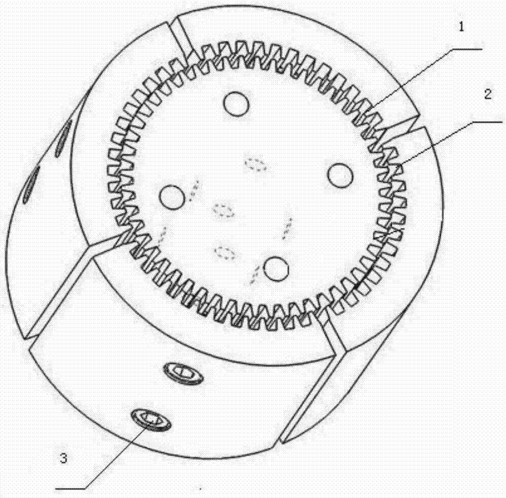
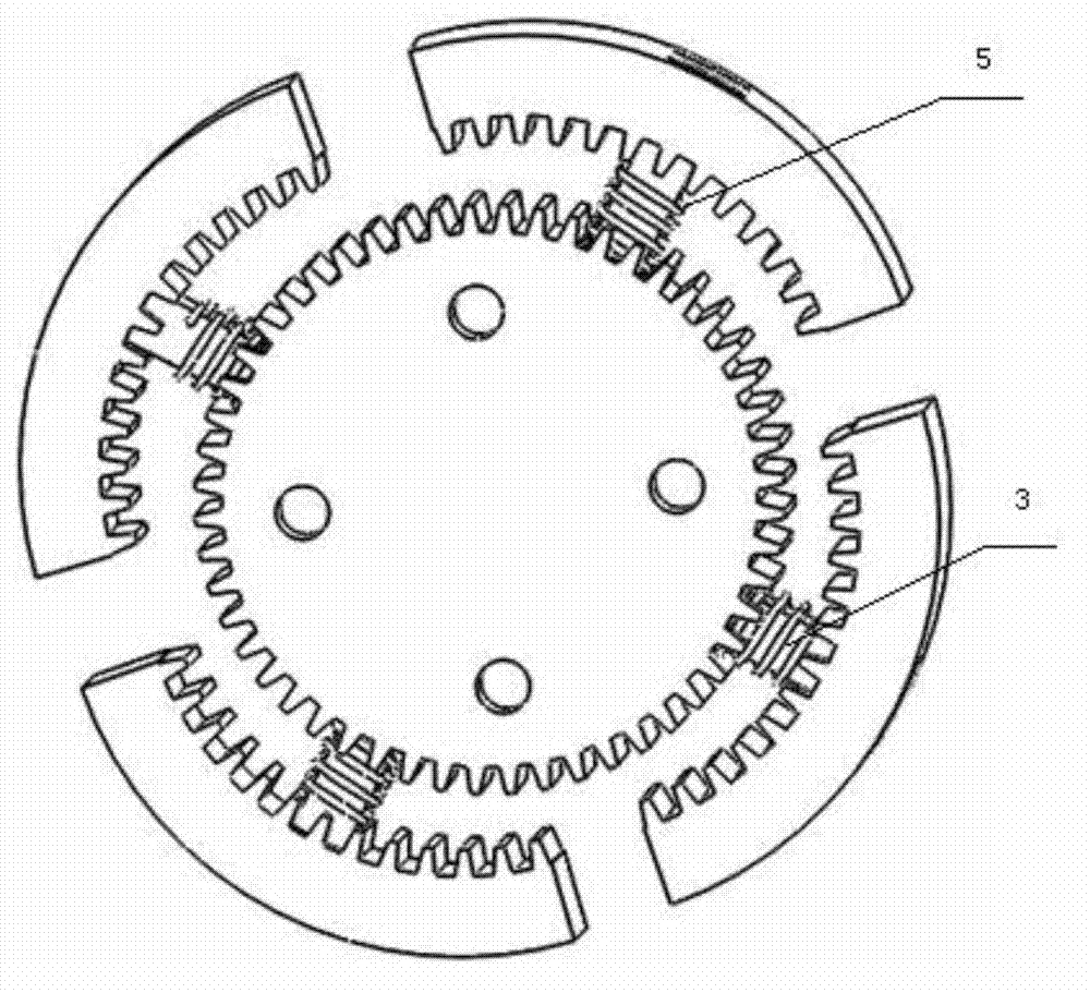
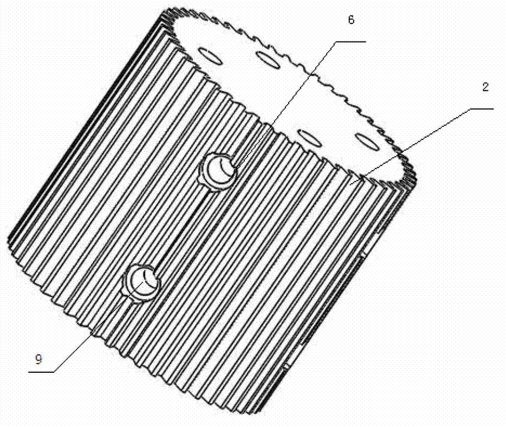
[0026] Figure 1-5 It is an embodiment of the 360° stress monitoring fiber grating microbend sensor of the present invention.

[0027] See figure 1 with image 3 , The inner shell of the cylinder adopts 360° toothing, that is, the tooth groove 2 is carved around the circumference of the cylinder in the direction parallel to the generatrix on its outer surface. The number, depth and width of the tooth grooves can be adjusted appropriately according to the size of the inner shell of the cylinder. In order to improve the sensitivity of the device, the optimal width of the cogging can be calculated according to the formula Where NA is the numerical aperture of the fiber grating, n is the core refractive index of the fiber grating, a is the core radius, M is the total mode number, and m is the guided mode number; the cross section of the tooth groove is trapezoidal; the tooth tip of the shell is smoothly polished , To prevent damage to the fiber grating when the shell is moved. In ...


PUM


Abstract

The invention discloses a 360-degree stress monitoring optical fiber grating microbend sensor. The 360-degree stress monitoring optical fiber grating microbend sensor comprises a circular cylinder inner shell, a sensing optical fiber grating, an outer shell, a connection piece and a spring, wherein a tooth groove which is perpendicular to an end face is machined on an edge circumference of the circular cylinder inner shell; the sensing optical fiber grating encircles the tooth groove; the outer shell surrounds the inner shell, and saw teeth which are coupled with the tooth groove of the inner shell are machined on the inner side surface of the outer shell; the connection piece is used for connecting the inner shell and the outer shell; and the spring is placed on the connection piece in a sleeved mode. In a natural state, the inner shell and the outer shell are tightly attached to the sensing optical fiber grating, but the sensing optical fiber grating is not enabled to deform. When an outside parameter acts on the outer shell, the sensing optical fiber grating is squeezed and bent, and the function of the outside parameter is learnt by measuring the central wavelength drift distance of the optical fiber grating. When the action of the outside parameter disappears, the outer shell returns under the action of the spring. According to the 360-degree stress monitoring optical fiber grating microbend sensor, 360-degree carved teeth are adopted, and the change of the outside parameter can be measured comprehensively. The sensing sensitivity is improved by adopting the optical fiber grating. Simultaneously, the optical time domain reflection technology can be utilized to conduct positioning testing, the position of a measured parameter is judged, and thereby real-time monitoring is achieved.

Description

Technical field [0001] The invention relates to the technical field of optical fiber grating sensing, in particular to a 360° stress monitoring optical fiber grating microbend sensor. Background technique [0002] The fiber grating microbend sensor is designed based on the bending of the fiber grating caused by the microbending and the shift of the center wavelength. The principle is that the center wavelength shifts due to the bending of the fiber grating modulated by the measured parameter. By detecting the shift of the center wavelength of the fiber grating To detect the measured parameter. When the external measured parameter changes, the fiber grating will be slightly bent periodically, and the degree of bending will change. At this time, the center wavelength of the optical signal passing through the fiber grating will change, so that the measured parameter can be detected. Variety. The fiber grating microbend sensor has the characteristics of anti-electromagnetic interfe...

Claims


Application Information

Patent Timeline
Patent Type & Authority Applications(China)
IPC IPC(8): G01L1/24
Inventor 徐军罗慕尧蒋晶张林秀
Owner HUAZHONG UNIV OF SCI & TECH
Learn More