Self-adaptive tracking probe applied to ultrasonic scanning detection

An adaptive tracking and ultrasonic scanning technology, which is applied in the direction of material analysis, measuring devices, and instruments using sound waves/ultrasonic waves/infrasonic waves, can solve problems such as lack of attitude and distance adaptive capabilities, difficulty in implementation, and limitations in engineering application effectiveness. Achieve the effect of adaptive tracking ability and effect, improved adaptive tracking ability, and good adaptive climbing ability

Active Publication Date: 2013-05-08
BEIJING AERONAUTICAL MFG TECH RES INST
View PDF8 Cites 6 Cited by
  • Summary
  • Abstract
  • Description
  • Claims
  • Application Information

AI Technical Summary

Problems solved by technology

For this reason, it is necessary to control the attitude and position of the ultrasonic probe by designing a special scanning mechanism, and realize 100% full-coverage scanning detection of different curved surface structures. The greater the technical requirements and cost of the scanning mechanism, the more difficult it is to realize, and the more limited and affected the practical effect of engineering applications
[0003] There are two main types of ultrasonic probes currently used for ultrasonic scanning detection: one is the single-probe method, in which the ultrasonic probe is designed as an independent rigid mechanical device, and the ultrasonic probe itself does not have the ability to self-adapt When detecting curved surface parts, it is necessary to control the ultrasonic probe by designing a special complex scanning mechanism, and realize the change of the attitude and position of the ultrasonic probe through the method of trajectory control, so as to realize the normal scanning detection of curved surface materials and their structures. The structure is an irregular three-dimensional space free-form surface, and the ultrasonic probe is a rigid structural entity, which has no attitude and distance self-adaptive ability. , the attitude and proximity adjustment of the ultrasonic probe, when the shape of the part to be tested is more complex, the numerical control system and scanning mechanism required are more complex, the implementation is more difficult, the engineering applicability is worse, the detection efficiency is lower, and the technical cost is extremely high The other is the ultrasonic transducer unit adaptive tracking method mentioned in the invention patent "A Ultrasonic Adaptive Tracking and Scanning Array Transducer" (Application No. 201110053880.5) of Beijing Aeronautical Manufacturing Engineering Research Institute: ultrasonic transducer The vertical motion raceway of the sensor adopts a circular closed vertical motion raceway sliding structure to adaptively adjust the upper and lower positions of the ultrasonic transducer unit, and the attitude of the ultrasonic transducer is adjusted through the universal swing angle joint. The disadvantages are: (1) Universal The swing angle joint is located in the inner cavity of the vertical motion raceway of the ultrasonic transducer. The adaptive tracking range of the ultrasonic transducer is limited by the open space of the vertical motion raceway inner cavity. For curved surface parts with a chord height greater than 100mm per meter and complex curvature changes Parts, it is difficult to realize the adaptive tracking of the ultrasonic transducer; (2) Ball contact sliding friction is adopted between the universal pendulum joint and the inner wall of the vertical motion raceway of the ultrasonic transducer, and the up and down movement flexibility of the universal pendulum joint It is limited, which affects the adaptive adjustment flexibility of the ultrasonic transducer. For parts with obvious curvature changes and complex curvature changes, the adaptive tracking ability and effect of the ultrasonic transducer are significantly affected.

Method used


Image

  • Self-adaptive tracking probe applied to ultrasonic scanning detection
  • Self-adaptive tracking probe applied to ultrasonic scanning detection
  • Self-adaptive tracking probe applied to ultrasonic scanning detection

Examples


Embodiment

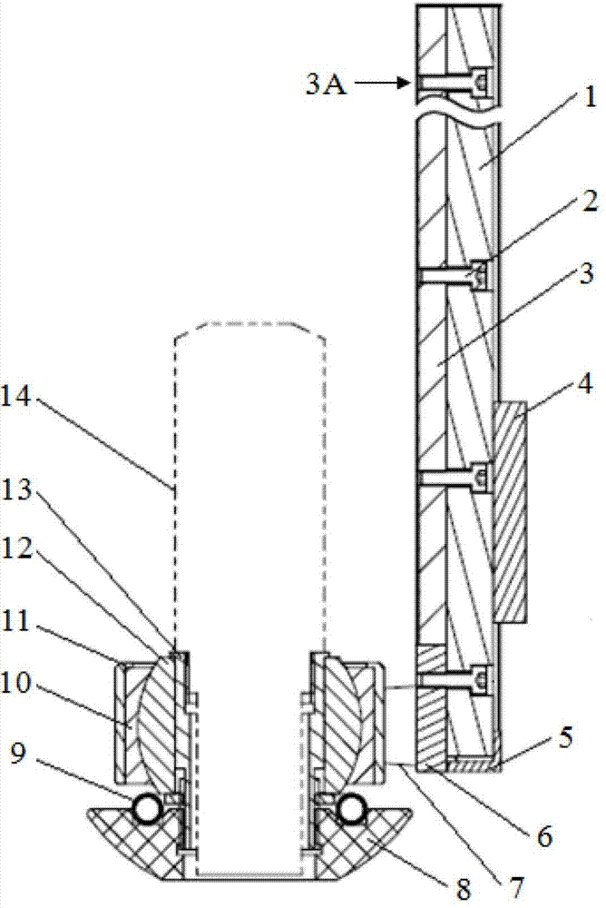
[0030] Using the self-adaptive tracking probe for ultrasonic scanning detection in the present invention, the CUS-6000 and CUS-21J series ultrasonic automatic testing equipment produced by Beijing Aeronautical Manufacturing Engineering Research Institute are used to match the self-adaptive tracking probe in the invention of this patent. , using the tracking method of the self-adaptive tracking probe of ultrasonic scanning detection in the present invention, a series of actual multi-curvature aircraft composite materials and metal parts with a length between 1000-6000mm and a chord height of 100mm and 200mm per meter have been carried out. Ultrasonic adaptive tracking scanning detection, during the automatic scanning process, the adaptive tracking probe always maintains flexible and good adaptive tracking and acoustic wave coupling with the surface of the part to be inspected with complex shapes, the detection signal display is very stable, and the adaptive tracking is stable and...


PUM


Abstract

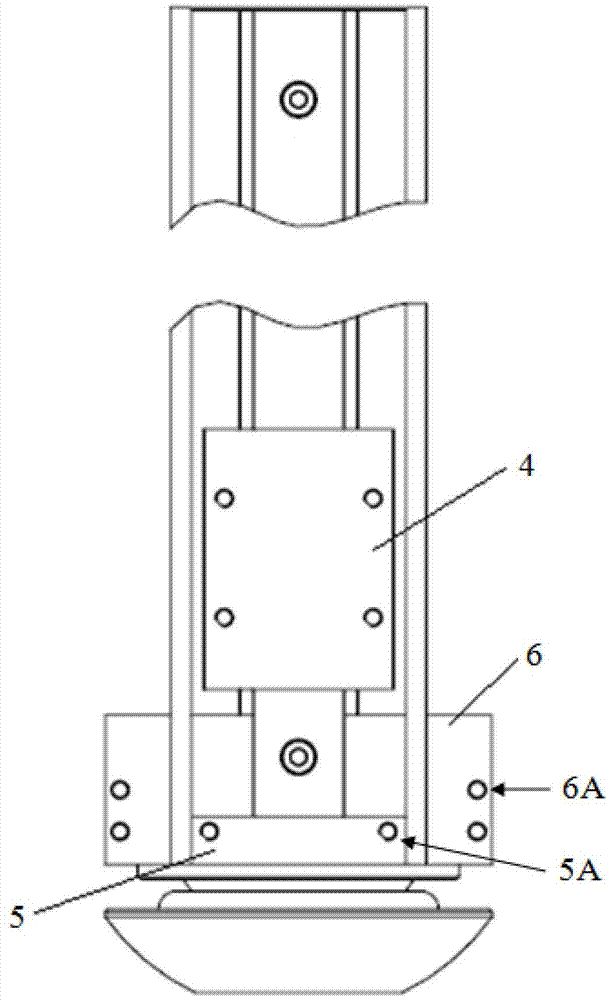
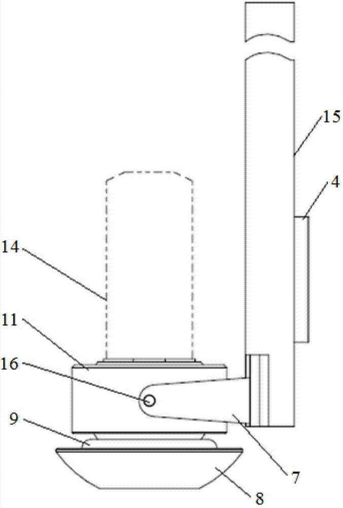
The invention relates to a self-adaptive tracking probe applied to ultrasonic scanning detection on materials and structures. The probe comprises a guide plate, a fixing bolt, a guide plate fixing base, a guide sliding plate, a lower baffle, a fixing plate, a rotating seat fixing support plate, a tracking contact, an elastic pad, a spherical rotating seat, a rotating seat fixing base, a spherical rotating head, an energy converter connecting sleeve, an ultrasonic energy converter, a guide protecting sleeve and a rotating shaft. According to the self-adaptive tracking method, the probe is connected with an external scanning mechanism; the sound wave coupling contact of a front end of the ultrasonic energy converter with the lower end surface of the tracking contact is formed at the surface of a detected part; the probe is moved; and the tracking probe drives the ultrasonic energy converter and the surface of the detected part to be in the shape surface and position contact, so as to realize the self-adaptive tracking scanning of the ultrasonic energy converter to the shape surface of the detected part. By utilizing the self-adaptive tracking probe, the self-adaptive tracking capability and flexibility of the ultrasonic energy converter to a curved surface part of which the chord height of each meter is larger than 100mm can be greatly improved, and the tracking range of the ultrasonic energy converter is greatly enlarged.

Description

technical field [0001] The invention belongs to the non-destructive testing technology, and relates to an adaptive tracking probe and an tracking method. Background technique [0002] Ultrasound is currently the main testing method used in the non-destructive testing of various materials and their structures in the world. One of the most important and widely used ultrasonic testing methods for non-destructive testing of materials is the ultrasonic scanning testing method based on the ultrasonic vertical pulse reflection method. Ultrasonic probe is the key unit of ultrasonic scanning inspection. It mainly realizes the scanning of the material and its structure and transmits / receives ultrasonic signals. During the scanning inspection process, it is necessary to ensure that the incident direction of the sound wave generated by the ultrasonic probe and the normal line of the detected point of the part Only when the direction is consistent can the normal transmission / reception ...

Claims


Application Information

Patent Timeline
Patent Type & Authority Applications(China)
IPC IPC(8): G01N29/24
Inventor 刘松平白金鹏刘菲菲李乐刚孟秋杰曹正华
Owner BEIJING AERONAUTICAL MFG TECH RES INST
Why Eureka
Try Eureka