Voltage detection circuit

A voltage detection circuit and voltage detection technology, applied in the direction of measuring current/voltage, voltage divider, measuring device, etc., can solve the problems of increasing the area, increasing the area occupied by the circuit, and slow comparator speed, so as to reduce the circuit area, The effect of reducing the circuit area and providing low-voltage alarm speed

Active Publication Date: 2013-05-08
SHANGHAI HUAHONG GRACE SEMICON MFG CORP
View PDF6 Cites 21 Cited by
  • Summary
  • Abstract
  • Description
  • Claims
  • Application Information

AI Technical Summary

Problems solved by technology

If in the same voltage detection circuit, a resistance detection circuit is used for both high voltage and low voltage, the high voltage and low voltage detection will not affect each other, but this will greatly increase the area occupied by the circuit on the chip, which will increase the cost.
[0004] In order to reduce the area of ​​the circuit, an existing method is to share a resistance detection circuit for the detection of high voltage and low voltage, but this common method has a disadvantage: if figure 1 As shown, in order to realize the detection of low voltage, the voltage divider V1 must be connected to the subsequent comparator for low voltage detection; in order to realize the detection of high voltage, the voltage divider V2 of the same resistor string must be connected to the subsequent comparator in a comparator that detects high voltage
When the detection voltage power supply V0 is a high voltage such as 6V, the divided voltage V1 is 4V, and the divided voltage V2 is 1V. Although the subsequent comparator used to detect the high voltage can work normally, since the divided voltage V1 is 4V, the subsequent use The working voltage of the comparator for detecting low voltage must be greater than 4V to work normally, that is, the comparator used for detecting low voltage must be made of high voltage devices such as 5V, and 5V devices directly cause the comparator to be slow and have a large area
Only two independent resistor strings can be used in occasions where fast low-voltage alarm is required, but this greatly increases the area

Method used


Image

  • Voltage detection circuit
  • Voltage detection circuit

Examples


Embodiment Construction

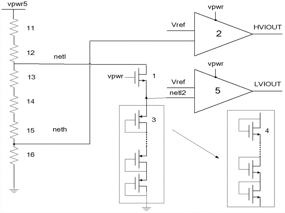
[0016] Such as figure 2 Shown is a schematic structural diagram of the voltage detection circuit of the embodiment of the present invention. The voltage detection circuit of the embodiment of the present invention includes:

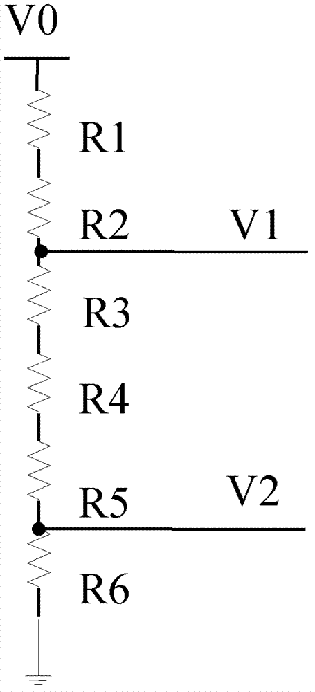
[0017] A resistance detection circuit, the resistance detection circuit is composed of a plurality of resistors connected in series and connected between the detection voltage power supply and ground, the detection voltage power supply is the first voltage power supply vpwr or the second voltage power supply vpwr5, the first voltage It should be lower than the second voltage, that is, the first voltage is low voltage and the second voltage is high voltage, low voltage such as 1.8V is supplied to low voltage devices, and high voltage such as 5V is supplied to high voltage devices. The series resistance of the resistance detection circuit divides the detection voltage power supply and takes out two divided voltages as the first voltage detection terminal ...


PUM


Abstract

The invention discloses a voltage detection circuit which can be used for detecting a lower first voltage power source and a higher second voltage power source. The same resistance detection circuit is used by both the higher voltage power source and the lower voltage power source, and a first voltage detection end which is separated from the resistance detection circuit is connected with a voltage protection circuit and then connected to a follow-up first comparator. The voltage protection circuit comprises a first N-channel metal oxide semiconductor (NMOS) tube with a high voltage and a transistor tandem cascading structure which is formed by connecting a plurality of diode-connected metal oxide semiconductor (MOS) tubes in series. When a high-pressure alarm is carried out, the voltage protection circuit enables the high voltage of the first voltage detection end to be released, the voltage which is input to the first comparator is enabled to be clamped in a low voltage and the first comparator is enabled to be produced by low-pressure devices, thus the speed of a low-pressure alarm is improved and the area of circuits is reduced. The voltage detection circuit is capable of greatly reducing the area of the circuits further by sharing the resistance detection circuit.

Description

technical field [0001] The invention relates to a semiconductor integrated circuit, in particular to a voltage detection circuit (VD). Background technique [0002] In the voltage detection circuit, in order to save area, the low-voltage alarm circuit and the high-voltage alarm circuit often share a resistor string, such as figure 1 As shown in FIG. 2 , it is a structural schematic diagram of the resistance detection circuit in the existing voltage detection circuit, that is, the resistance string. figure 1 In the resistance detection circuit, resistors R1, R2, R3, R4, R5 and R6 are connected in series between the detection voltage power supply V0 and the ground. Resistors R1, R2, R3, R4, R5, and R6 divide the detection voltage power supply V0, and the divided voltages at the connections of each resistor can be taken out separately, as figure 1 The divided voltage V1 and the divided voltage V2 can be taken out, and the divided voltage V1 and the divided voltage V2 can be r...

Claims


Application Information

Patent Timeline
Patent Type & Authority Applications(China)
IPC IPC(8): G01R15/04G01R19/00
Inventor 唐成伟
Owner SHANGHAI HUAHONG GRACE SEMICON MFG CORP
Why Eureka
Try Eureka