
Electric energy meter dynamic measurement cycle power sequence proportional allocation calibration method

A technology of dynamic measurement and proportional distribution, applied in the measurement of electrical variables, measurement devices, instruments, etc., can solve the problem of inability to give measurement traceability errors.

Inactive Publication Date: 2013-05-08
STATE GRID CORP OF CHINA +1
View PDF5 Cites 27 Cited by
  • Summary
  • Abstract
  • Description
  • Claims
  • Application Information

AI Technical Summary

Problems solved by technology

[0004] The present invention aims to solve the problem that the power signal source is used to generate the dynamic load electric energy signal in the existing dynamic performance measurement test of the electric energy meter, and the measurement traceability error cannot be given. test method

Method used


Image

  • Electric energy meter dynamic measurement cycle power sequence proportional allocation calibration method
  • Electric energy meter dynamic measurement cycle power sequence proportional allocation calibration method
  • Electric energy meter dynamic measurement cycle power sequence proportional allocation calibration method

Examples


specific Embodiment approach 1

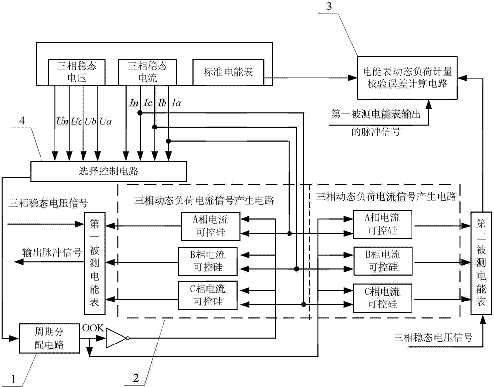
[0034] Specific implementation mode one: the following combination figure 1 Describe the present embodiment, the electric energy meter dynamic metering cycle electric energy sequence proportional distribution verification method described in the present embodiment, it adopts three-phase steady-state voltage signal or three-phase steady-state current signal to generate synchronous on-off control signal OOK through cycle distribution circuit 1 , the on-off control signal OOK generates a dynamic load current signal through the three-phase dynamic load current signal generating circuit 2, and the dynamic load current signal is input to the measured electric energy meter in the form of a discrete electric energy sequence; the three-phase dynamic load current signal generates Circuit 2 uses a three-phase steady-state current signal as a working power supply; the measured electric energy meter uses a three-phase steady-state voltage signal as a working power supply;

[0035] Then col...

specific Embodiment approach 2

[0037] Specific implementation mode two: the following combination figure 1 Describe this embodiment, this embodiment is a further description of Embodiment 1, the synchronous on-off control signal OOK s(t) described in this embodiment is:

[0038] s ( t ) = Σ n a n g ( t - nT ) ,

[0039] where a n is the discrete electric energy sequence of the dynamic load current signal, n is the serial number of the discrete electric energy sequence, a n The expression is:

[0040]

[0041] t is time, T is 50Hz power frequency AC cycle,

[0042] rectangular window function

[0043] N is a natural number;

[0044] OOK dynamic load time domain instantaneous current i in the nth control cycle under the synchronous on-off control signal OOK contro...

specific Embodiment approach 3

[0062] Specific implementation mode three: this implementation mode is a further description of implementation mode two, and the T A and T B The number ranges from 1 to 2000.


PUM


Abstract

The electric energy meter dynamic measurement cycle power sequence proportional allocation calibration method belongs to the technical field of electric energy meter dynamic performance measurement. The electric energy meter dynamic measurement cycle power sequence proportional allocation calibration method solves the problem that a power signal source is adopted to produce dynamic load electric energy signals, and therefore measurement tracing error can not be given out in the existing dynamic performance measurement test of an electric energy meter. The electric energy meter dynamic measurement cycle power sequence proportional allocation calibration method adopts synchronous on-off keying (OOK) cycle on-off control signals generated from three-phase steady-state voltages or three-phase steady-state current signals to dynamically distribute the three-phase steady-state current signals, by using a power electronic component, such as controllable silicon, transient state, short time and long time three kinds of periodically-changed dynamic load current signals are controlled to be produced, and dynamic load power is input into the electric energy meter under test in a discrete electric energy sequence mode. Dynamic load measurement validation error of the electric energy meter under the test is calculated by collecting output impulse of a standard electric energy meter and the electric energy meter under the test, and dynamic load measurement test tracing of the electric energy meter under the test can be achieved. The electric energy meter dynamic measurement cycle power sequence proportional allocation calibration method is suitable for validation of electric energy meters.

Description

technical field [0001] The invention relates to a method for verifying the proportional distribution of electric energy series in a dynamic measurement period of an electric energy meter, and belongs to the technical field of dynamic performance measurement of electric energy meters. Background technique [0002] In recent years, with the development of industrial technology, the dynamic power load in the power system has been increasing, such as: high-power silicon rectifier equipment used in electrified railways, AC electric arc furnaces and AC inverter devices used in iron and steel enterprises, petrochemical High-power electric drive equipment and motor frequency conversion speed control devices, construction tower cranes and welding equipment used in industries such as machinery and machinery. These dynamic loads are mainly manifested as: the instantaneous load current is severe, the fluctuation is large-scale up and down, and the sub-harmonic wave changes with time, et...

Claims


Application Information

Patent Timeline
Patent Type & Authority Applications(China)
IPC IPC(8): G01R35/04
CPCG01R35/04
Inventor 陆以彪王学伟韩东王琳齐传凤吕华李鹏万静
Owner STATE GRID CORP OF CHINA
Learn More