Space target high resolution imaging method based on high resolution range profile (HRRP) sequence

A space target and imaging method technology, applied in the field of radar imaging and signal processing, can solve problems such as high computational complexity, random initial phase error of echo phase, and movement of scattering points beyond the distance unit

Active Publication Date: 2013-05-08
XIDIAN UNIV
View PDF1 Cites 24 Cited by
  • Summary
  • Abstract
  • Description
  • Claims
  • Application Information

AI Technical Summary

Problems solved by technology

However, while obtaining high resolution in the range direction, if the traditional imaging method is still used to obtain high resolution in the azimuth direction, new problems will be encountered: First, the improvement of the range resolution will make it easier for the scattering points to move beyond the distance unit , thus limiting the application of imaging methods such as distance-instantaneous Doppler and time-frequency analysis; secondly, because electromagnetic waves are affected by atmospheric disturbances, the echo phase will contain time-varying random initial phase errors
However, the shortcomings of this method are that when the traditional adjacent correlation translation compensation method fails due to the serious movement of the scattering point over the distance unit, the effective translation compensation method is not considered; when the target has variable acceleration rotation, or the radar When performing repetition frequency dithering (that is, pulse repetition frequency changes with time) to realize ECCM (electronic counter-countermeasures), the sinusoidal model assumed by this method is no longer satisfied, resulting in blurred images; at least one rotation period of the target needs to be received Only echoes can get low sidelobe and well-focused images. When the number of echoes is small, the sidelobes are high; the computational complexity is high

Method used


Image

  • Space target high resolution imaging method based on high resolution range profile (HRRP) sequence
  • Space target high resolution imaging method based on high resolution range profile (HRRP) sequence
  • Space target high resolution imaging method based on high resolution range profile (HRRP) sequence

Examples


Embodiment Construction

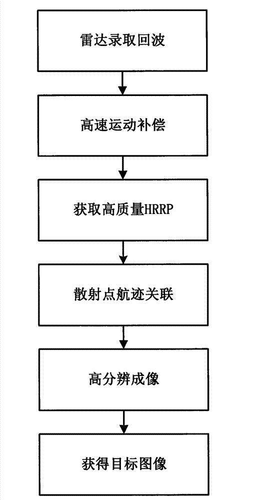
[0050] Attached below figure 1 , the specific embodiment of the present invention is described in further detail:

[0051] Step 1. The radar records the inverse synthetic aperture ISAR echo of the target. The radar transmits and receives the pulse at the pulse repetition frequency, and obtains the ISAR echo with the distance as the row vector and the azimuth as the column vector.

[0052] Step 2, high-speed motion compensation

[0053] 2a) The reference distance is the distance from the radar to the center of the scene, and the chirp signal with the same frequency and frequency as the radar transmitted signal is used as the reference signal, where the reference signal is as follows:

[0054] S ( t ^ , t 1 ) = rect ( t ^ ...


PUM


Abstract

The invention discloses a space target high resolution imaging method based on a high resolution range profile (HRRP) sequence. The space target high resolution imaging method includes a first step of recording inverse synthetic aperture radar (ISAR) echo through a radar, a second step of obtaining high-speed motion compensation, a third step of obtaining high quality HRRP, a fourth step of carrying out scattering point flight path correlation, and a fifth step of achieving high resolution imaging. Firstly, through sparse signal reconstruction, the high quality HRRP sequence can be obtained, then an effective flight path correlation method is adopted to generate a scattering point flight path matrix in the HRRP sequence, and further, through matrix decomposition with a constraint condition, the high resolution imaging can be achieved. The method overcomes the defects that a transforming method based on subsection false Keystone is high in requirements for pulse repetition frequency (PRF), strict in requirements for a target motion model, big in difficulty in accurate translation compensation and phase correction to a high-speed rotating target in the imaging process, big in the amount of calculation and the like, and has the advantages of being capable of carrying out high resolution imaging on the conditions of low PRF and even direction Doppler blur, and having universality to the target motion model, being free from translation compensation, high in efficiency, good in image focusing, and the like.

Description

technical field [0001] The invention belongs to the technical field of signal processing, and further relates to a high-resolution imaging method for space targets based on a high-resolution range profile (high-resolution range profiles, HRRP) sequence in the field of radar imaging. The present invention can effectively perform high-resolution imaging on space targets under the condition of low repetition frequency, avoids the influence of azimuth undersampling, translational motion and random initial phase errors on image quality, and provides a strong guarantee for subsequent target recognition. Background technique [0002] In order to obtain a finer and more accurate description of the distribution characteristics of space target scattering points, the requirements for the resolution of radar images are constantly increasing. Among them, the high resolution in the range direction is obtained by transmitting a large time-width-bandwidth product signal; while the high reso...

Claims


Application Information

Patent Timeline
Patent Type & Authority Applications(China)
IPC IPC(8): G01S13/90
Inventor 白雪茹周峰刘妍保铮
Owner XIDIAN UNIV
Why Eureka
Try Eureka