
Mode control cascading-type liquid crystal micro lens array

A liquid crystal microlens, mode control technology, applied in nonlinear optics, instruments, optics, etc., can solve the problems of increasing the response speed, the gradient refractive index curve is not smooth enough, etc., to achieve the effect of fast response speed and smooth contour.

Active Publication Date: 2013-05-08
SOUTHEAST UNIV
View PDF4 Cites 7 Cited by
  • Summary
  • Abstract
  • Description
  • Claims
  • Application Information

AI Technical Summary

Problems solved by technology

Compared with the first type of liquid crystal lens in the early stage, the advantage of this type of lens is that the response time is consistent during the focusing process, and there is no light scattering phenomenon. The gap, the thickness of the liquid crystal lens is generally larger, which increases the driving voltage and increases the response speed

Method used


Image

  • Mode control cascading-type liquid crystal micro lens array

Examples


Embodiment 1

[0028] Embodiment 1, cascaded liquid crystal microlens concave lens array:

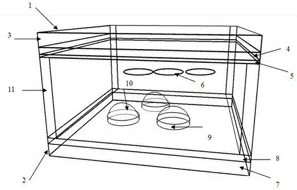
[0029] Including an upper substrate 1, a lower substrate 2, a liquid crystal layer 6, and a pad 11, the upper substrate 1 includes an upper substrate glass 3, an upper substrate ITO film 4, and an upper substrate alignment layer 5 from top to bottom; the lower substrate 2 includes lower substrate glass 7, lower substrate ITO thin film 8, high surface resistance layer 9, polymer solid lens and photo-alignment layer 10, wherein pattern etching is carried out on the lower substrate ITO thin film 8 according to the required pixel size and shape, figure 1 Shown is circular hole pixel pattern etching, the high surface resistance layer 9 is formed by a ZnO layer with a surface resistance value in the range of 0.1-10 MΩ / sq or an ITO layer prepared under specific parameters, and the radius of the polymer solid convex lens 10 is the same as that of the circular hole engraved The eclipse radius is the same, and ...

Embodiment 2

[0033] Embodiment 2, cascaded liquid crystal microlens convex lens array:

[0034] The implementation structure diagram is still as figure 1 As shown, what is changed is the refractive index of the polymer lens. In the case of embodiment two (n o e 1 -L 2 1 -L 2 2 / 2(n e -n) h~r 2 / 2(n o -n) h, where r is the radius of the polymer lens.

[0035]

Embodiment 3

[0036] Embodiment 3, a cascaded liquid crystal microlens array for conversion of concave lenses and convex lenses:

[0037] The example case (n o e ), when not powered, L 1 -L 2 >0, it is a concave lens; in the power-on state, L 1 -L 2 2 / 2(n e -n) h~r 2 / 2(n o -n) h, where r is the radius of the polymer lens.


PUM

PropertyMeasurementUnit
thicknessaaaaaaaaaa
refractive indexaaaaaaaaaa

Abstract

The invention discloses a mode control cascading-type liquid crystal micro lens array, relates to a liquid crystal micro lens array, and particularly relates to the technical field of mode control cascading-type liquid crystal micro lens arrays. The mode control cascading-type liquid crystal micro lens array comprises an upper substrate, a lower substrate and an internal packaging liquid crystal layer wherein the upper substrate and the lower substrate are arranged in parallel, the upper substrate includes upper substrate glass, a grounding electrode layer and an upper substrate alignment layer, the upper substrate glass, the grounding electrode layer and the upper substrate alignment layer are arranged in sequence, the lower substrate includes lower substrate glass, a contact electrode layer, a high surface resistance layer, a polymer solid lens and light an alignment layer, a gasket is arranged between the upper substrate alignment layer and the contact electrode layer in a distributed mode, and the internal packaging liquid crystal layer is formed by the upper substrate alignment layer, contact electrode layer and a gasket. According to the mode control cascading-type liquid crystal micro lens array, the purposes of being adjustable in focal distance, low in driving voltage and fast in response speed and time are achieved.

Description

[0001] technical field [0002] The invention relates to a liquid crystal microlens array, in particular to the technical field of a cascaded liquid crystal microlens array. [0003] Background technique [0004] Liquid crystal microlens technology, its focal length can be controlled by voltage. The traditional solid lens needs to combine different lenses and adjust the distance between the lenses to control the change of the focal length. In comparison, the biggest advantage of liquid crystal microlenses is that they are small in size, save bulky mechanical devices, and can obtain adjustable focal length characteristics, also known as adaptive lenses. Therefore, it has great potential application value in the fields of optical interconnection, adaptive optics, photoelectric storage, and integrated optical display. [0005] Common liquid crystal adaptive lenses, generally speaking, there are three methods to produce gradient refractive index profiles similar to traditiona...

Claims


Application Information

Patent Timeline
Patent Type & Authority Applications(China)
IPC IPC(8): G02F1/29G02F1/1337G02F1/139G02F1/133
Inventor 李青崔勇扬严静胡凯刘佩琳
Owner SOUTHEAST UNIV
Learn More